
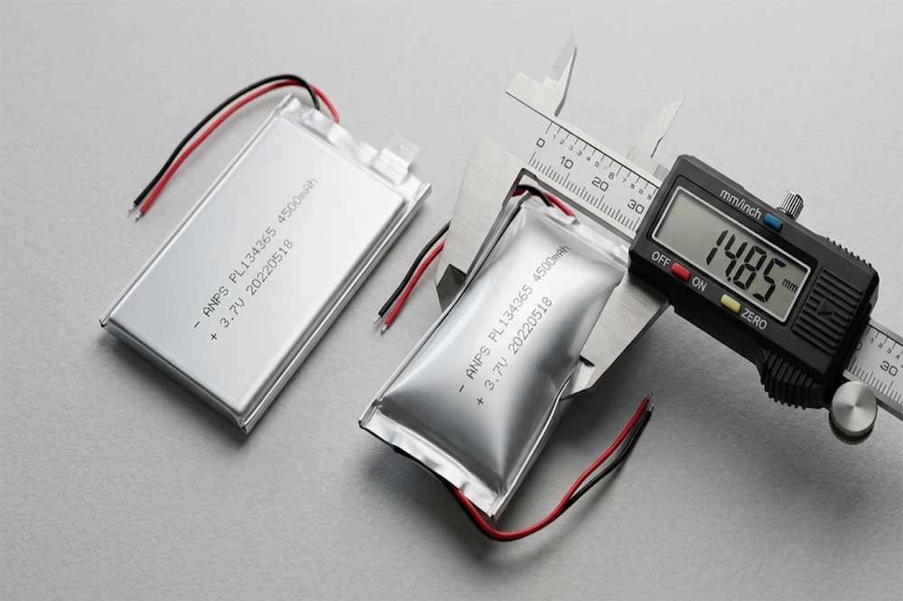
A lithium ion pouch cell that has swollen is one of the few battery problems you can see with your eyes before it becomes a field failure. The aluminum-plastic laminate bulges, the cell no longer sits flat in its housing, and in a slim device the cover starts to lift.
Most engineers meet this problem at the worst possible moment — during pilot production, during reliability testing, or after a batch has already shipped. And the first reaction is usually the same: is this normal thickness growth, or is this a cell that is going to fail?
This guide answers that question in order. What swelling actually is, where the gas comes from, which causes account for most real-world cases, what the risks are at the pack and product level, and how to prevent it during design, production and use. It is written for OEM and ODM teams sourcing lithium ion pouch cells rather than for a laboratory audience.
What Counts as Swollen Pouch Cell?
A pouch cell is wrapped in a three-layer laminate: a polymer outer layer, an aluminum foil barrier, and an adhesive inner layer. Unlike a steel can or an aluminum prismatic shell, this package has almost no structural stiffness. Any internal pressure shows up immediately as a change in shape.
That is the key point. A pouch cell is a pressure indicator by design. Cylindrical and prismatic cells also generate gas, but the rigid housing hides it until internal pressure is much higher.
In practice, three different things get called “swelling”, and they have very different meanings:
| What you observe | What it usually is | Urgency |
| Uniform, soft puff across the whole face; thickness up 3–8%; returns partly when pressed gently | Normal gas from SEI formation and electrolyte wetting in early life | Low — monitor |
| Progressive, even swelling that keeps growing cycle after cycle; capacity fading in parallel | Ongoing electrolyte decomposition, high-temperature aging, mild overcharge | Medium — investigate |
| Localized hard bump, sharp edge, “pillowing” near a tab, or a sudden jump in one cycle | Internal short precursor, tab weld defect, seal failure, lithium plating | High — quarantine |
If you only remember one thing from this article: rate matters more than absolute thickness. A cell that gains 4% in 500 cycles is behaving. A cell that gains 4% in 20 cycles is telling you something is wrong.
Where the Gas Comes From
The bulge is gas, and the gas comes from the breakdown of the liquid inside the cell. A pouch cell contains a flammable organic electrolyte — typically a mixture of ethylene carbonate, ethyl methyl carbonate or dimethyl carbonate, with LiPF₆ salt and small amounts of additives. When that solvent or the salt decomposes, it produces CO₂, CO, H₂, C₂H₄ and other light hydrocarbons. None of them can leave. The laminate does not vent until internal pressure is far above the level at which the cell has already visibly deformed.
Four reaction routes account for nearly all of it:
1. SEI formation and repair. The solid electrolyte interphase on the anode consumes electrolyte and releases gas during the first charge. Some of this is unavoidable and is worked off during formation and aging at the factory. But every time the SEI cracks — from thermal stress, mechanical stress, or silicon anode expansion — it re-forms and releases more gas.
2. Electrolyte oxidation at the cathode. Above the designed charge voltage, the cathode becomes unstable and oxidizes the electrolyte. Layered oxides such as LCO and NMC can also release lattice oxygen when over-delithiated, which then reacts with the electrolyte. This is why overcharge produces gas quickly and why it is the most common cause of dramatic swelling.
3. Water ingress and HF attack. LiPF₆ reacts with trace moisture to form HF and PF₅. HF attacks the cathode and the SEI, generating more gas, and water is reduced at the anode to produce hydrogen. The source of the water is often not the electrolyte but a poor heat seal or a damaged aluminum-plastic film that lets humidity in over months of storage.
4. Lithium plating. When lithium deposits as metal on the anode instead of intercalating — at low temperature, at high charge rate, or on a locally over-compressed electrode — the plated lithium reacts directly with the electrolyte. The result is gas plus electrically isolated “dead lithium”, so capacity falls as the cell puffs.
The Main Causes, in Order of How Often They Occur
Overcharge and Over-Discharge
Overcharge is the single most destructive common cause. Pushing a 3.7 V cell past 4.2 V drives cathode-side electrolyte oxidation and, in severe cases, oxygen release. Gas generation accelerates, temperature rises, and the cell can go from “slightly puffy” to “failed” within a few cycles.
Over-discharge is subtler but equally damaging. Below roughly 2.0 V the copper anode current collector begins to dissolve into the electrolyte. On the next charge, that copper re-deposits as dendrites rather than as a foil, which creates an internal short path and, with it, local heating and gas. A pack that was stored flat for a year and then charged without a low-voltage cutoff check is a classic case. The voltage window and cutoff behaviour of a pouch cell is worth reviewing before you finalise BMS thresholds.
The practical rule: a protection circuit must be verified on the pack, not only on the cell datasheet. One weak cell in a series string will be driven into overcharge by the stronger ones, which is why cell matching matters as much as the BMS.
High-Temperature Operation and Storage
Heat accelerates every decomposition reaction in the cell. Storage at full charge in a warm warehouse is the most common abuse in the supply chain, and it happens before the cell ever reaches your production line.
The worst-case combination is well known in the industry: 100% state of charge held at 45 °C or above. Under those conditions SEI growth and electrolyte reduction proceed continuously, thickness climbs, and impedance rises. A cell stored this way for six months may show visible swelling before it has completed a single cycle in your product.
Warm locations inside the device matter too. Placing the pouch cell directly against a charging IC, a power amplifier, or a motor driver creates a local hot spot that ages one area of the electrode much faster than the rest — and that is exactly the condition that produces a hard localized bump rather than an even puff.
Moisture, Electrolyte Quality and Formation Process
Two cells built to identical drawings can behave completely differently depending on process control. Residual moisture in the electrode or separator, an electrolyte with a water content above specification, an incomplete formation cycle, or insufficient vacuum sealing during degassing will all leave a cell that swells early.
This is a factory-side cause, and it is the one buyers can influence most directly — through supplier selection and incoming inspection rather than through design changes. The manufacturing sequence for pouch cells shows where the critical controls sit: dry-room humidity, electrolyte filling under vacuum, formation and aging, and final degassing and resealing.
Mechanical Damage and Seal Failure
The laminate is tough but it is not a metal can. A burr on a housing rib, a screw head pressing into the cell face, a tab bent repeatedly during assembly, or a nick on the edge fold during handling can all compromise the barrier layer. Moisture enters, HF forms, gas appears — often weeks later, which makes the root cause hard to trace.
Tab sealing is a specific weak point. The heat-seal region around the tabs has to bond through several material transitions, and a weak seal there will pass a visual inspection and still leak slowly.
Cell Mismatch in Multi-Cell Packs
In a series string, capacity, impedance and self-discharge differences translate directly into voltage differences. The BMS will cut off on the highest cell and the lowest cell drifts further down each cycle, or the balancer will hold the string at a voltage that overcharges the weakest cell. Either way, one cell spends its life outside the safe window and swells first. A pack where a single cell puffs is usually a matching problem, not a cell chemistry problem.
Enclosure Design That Gives the Cell Nowhere to Go
This cause is entirely self-inflicted. If a pouch cell is clamped between two rigid surfaces with zero clearance, the normal 2–4% thickness growth of early life has to go somewhere. It goes into the electrode stack as compressive stress, which reduces porosity, raises local current density, and accelerates plating and gas generation. The cell then swells faster because it was not allowed to swell at all.
What Are the Actual Risks?
Swelling is a symptom, not the disease. The risks fall into four groups.
Performance loss. Capacity fade and impedance rise track thickness growth closely. A pack that has swelled 8% typically has lost a meaningful share of its usable capacity, and its voltage sag under load will be worse.
Mechanical damage to the product. In a slim device, a 0.5 mm bulge is enough to lift a cover, stress a display, crack a touch panel adhesive, or break the seal of an IP-rated enclosure. This is the failure mode that reaches customers first, and it is often reported as a housing defect rather than a battery defect.
Safety events. A swollen cell has, by definition, an altered internal geometry. Gas pockets create dry regions where ion transport stops, current concentrates at the edges of those regions, and lithium plates there. A hard localized bump is a warning that an internal short may already exist. A pouch cell has no pressure-relief vent, so a thermal event ruptures the laminate and ejects hot material rather than venting through a designed port. The wider pattern of swelling leading to fire in UAV packs applies just as much to handheld and medical devices, where the cell may be against the user’s body.
Commercial and compliance cost. A swollen cell fails UN38.3 testing and cannot be legally air-freighted as a standalone shipment. It will also fail most customer reliability specifications, and it triggers field returns, warranty claims and re-engineering costs that dwarf the cell price. For a medical or wearable product, the certification impact alone can delay a launch by months.
Prevention, Part 1: Design Decisions
Set a real thickness allowance. Design the enclosure with 8–10% thickness headroom over the fresh cell, and use a compressible gap filler or foam pad rather than a hard clamp. The pad should be specified with a known compression curve, not chosen by feel. Allow the cell to breathe; do not pre-load it to the point where early-life gas has nowhere to go.
Choose the chemistry and electrolyte for the duty cycle. If the product charges to 4.2 V and sits on a desk at 35 °C, ask the supplier for an electrolyte additive package designed for that. Vinylene carbonate, fluoroethylene carbonate and similar additives stabilise the SEI and measurably reduce long-term gas. For LFP cells the voltage ceiling is lower and the gas profile is different, but the principle is the same: match the electrolyte to the actual voltage and temperature window, not to a generic specification.
Derate the charge voltage if runtime allows. Charging to 4.1 V instead of 4.2 V typically costs 8–10% capacity and buys a significant reduction in both gas generation and capacity fade. For devices that are charged nightly and used lightly, this is the cheapest reliability improvement available.
Specify the BMS window explicitly. Over-voltage cutoff, under-voltage cutoff, over-current, and temperature-limited charging are baseline. Charging must be inhibited below 0 °C and above roughly 45 °C. If the product can be left on a charger in a hot car, add a charge-resume hysteresis so the pack does not sit at full voltage while hot.
Protect the laminate mechanically. Round every edge the cell touches, add strain relief on the tabs, and never let a screw, a rib or a connector press on the cell face. If the cell sits in a stack, check that the pressure is uniform and that no single point carries the load.
Size the cell with headroom. Running a cell at 95% depth of discharge every cycle accelerates aging and gas generation. Selecting one capacity step up so the typical cycle stays within 80% depth of discharge is often cheaper than the warranty cost of a marginal design. This is the same calculation described in choosing the right mAh and Ah, viewed from the reliability side.

Prevention, Part 2: Manufacturing and Incoming Quality
Design gets you a cell that can survive. Process control gets you a cell that does.
Measure thickness, don’t assume it. Every cell should be measured after formation and again after aging, under a defined pressure and at defined points. The delta between the two is one of the most useful screening signals available, and it costs almost nothing to record.
Use aging and self-discharge sorting. A 5–7 day aging period at elevated temperature followed by OCV and AC internal resistance measurement catches the cells that would have swollen in the field. Sorting by K-value (open-circuit voltage drop per day) removes the low-level internal short candidates before they are built into a pack.
Control moisture at the source. Dry-room dew point, electrolyte water content, and seal integrity are the three parameters to audit at the supplier. Ask for the actual control limits, not the marketing statement.
Test the failure modes, not just the specification. Overcharge to cutoff failure, external short, nail penetration, crush and thermal exposure on a sample basis will tell you how a given design behaves when it goes wrong — which is different from whether it passes a routine acceptance test. Our own quality control process runs these as part of batch release rather than as a one-off type test.
Inspect incoming lots. Thickness, OCV, ACIR, capacity and dimensional check on an AQL sample. Record the batch and the formation date. When a swelling issue appears eighteen months later, that record is what makes a root-cause investigation possible.

Prevention, Part 3: Storage, Handling and Use
Most swelling incidents in the field trace back to something simple:
- Store at 15–25 °C and around 40–60% state of charge for anything longer than a month. Full-charge storage is the most common avoidable mistake.
- Never charge below 0 °C. Plating at low temperature is fast, permanent and gassy.
- Do not solder directly to tabs without a heat sink, and never let a soldering iron dwell on the seal area.
- Do not puncture, crease or fold a cell to make it fit. A crease through the electrode stack creates a local short path.
- Check voltage before use after long storage. A cell below 2.0 V should be quarantined, not “woken up” with a slow charge.
- Ship at 30% state of charge or below by air, with UN38.3 test documentation on file. Our battery certifications page lists what is available per product family.
If a Cell Has Already Swollen
Do not try to fix it. The correct sequence is short:
- Stop using the device or pack immediately, and do not attempt another charge.
- Isolate the cell in a non-flammable container — a metal box or a ceramic dish — away from anything combustible, in a ventilated area.
- Do not puncture, compress, freeze or immerse it to “see what happens”. Puncturing a swollen cell is the single most reliable way to start a fire.
- Monitor for 24 hours. If it becomes hot, starts to smoke, or vents, evacuate and call emergency services.
- Do not return it through normal courier channels. Use a licensed hazardous-waste or battery-recycling route.
- Photograph the cell, record the batch code, cycle count and storage conditions, and send it to the supplier. A swelling claim without data cannot be investigated.
Choosing a Supplier Who Does Not Treat Swelling as Normal
Because a pouch cell is a pressure gauge, a supplier’s process discipline becomes visible in the product. Three questions separate a controlled factory from an assembler:
- What is your thickness measurement protocol after formation and aging, and what is the rejection limit? A supplier with a number answers in seconds. A supplier without one has never screened for it.
- What is the electrolyte water content limit and how is the dry room monitored? Vague answers here predict early swelling.
- Can you supply aging and K-value sorting data with the batch? If the data exists, it can be shared.
Beyond the process, the mechanical build matters: seal width, tab seal design, and edge fold quality are visible on a cross-section. A supplier who can show you those cross-sections under a microscope is usually controlling the variables that cause swelling. Our own production process is documented step by step for exactly this reason — buyers should be able to audit it.
Matching the Cell to the Application
Swelling risk is not uniform across products. A few patterns are worth knowing:
- Wearables and slim handhelds have the least thickness headroom and the highest visibility of any bulge. Cells here need the tightest incoming thickness screening and the most generous enclosure allowance. Small formats such as a 3.7V 500mAh pouch cell are typical, and they are also the easiest to over-compress during assembly.
- Handheld terminals, GPS units and medical monitors are usually charged nightly and left at full charge. Derating the charge voltage and adding a charge timer has a disproportionate effect on life.
- Higher-capacity packs for portable instruments and power tools carry more absolute gas volume, so a small percentage of swelling becomes a visible millimetre. A 3.7V 15Ah pouch cell at 6% growth is a 0.6 mm change on an 11 mm cell — enough to break a rigid enclosure design.
- Multi-cell packs such as a 3S 11.1V pouch pack need cell matching and balancing, because a single drifting cell is the most common source of localized swelling in a pack that otherwise looks fine.
One more question comes up often: is a lithium polymer cell more prone to swelling than a lithium ion pouch cell? In practice they are the same construction — the difference is in naming and chemistry rather than in packaging, so the swelling behaviour follows the same rules.

Conclusion
Lithium ion pouch cell swelling is a rational response to a specific set of conditions. Gas is produced when the electrolyte decomposes, and the electrolyte decomposes when the cell is pushed outside its voltage, temperature or mechanical window — or when moisture gets in.
That makes the problem controllable. Give the cell thickness headroom, keep it inside its voltage and temperature limits, screen thickness and self-discharge at the factory, store it at partial charge, and never let a swollen cell back into a product. None of these measures is expensive. All of them depend on a supplier who measures and records what actually happens inside the cell.
If you are designing a product around a pouch cell and want to discuss thickness allowance, BMS thresholds or electrolyte selection, our team can review the application and recommend a cell and pack configuration that fits. Browse the full pouch cell range or send us your specifications.
FAQs
It should be treated as unsafe until proven otherwise. A swollen cell has altered internal geometry, which can concentrate current and promote lithium plating. A hard, localized bulge is a stronger warning sign than an even, soft puff. Stop using it, isolate it away from combustible material, and do not puncture or compress it.
A small amount of early-life gas can partially reabsorb, especially if the cell is cycled gently and the gas is consumed at the anode. Permanent swelling — where the laminate has been stretched beyond its elastic limit, or where solid decomposition products have formed — does not reverse. If thickness does not come down after a few gentle cycles, treat the cell as degraded.
There is no universal number, but a practical framework: 2–5% growth over the first 50 cycles and under about 8% at end of life is common for consumer pouch cells. What matters most is the rate. A sudden jump, or more than about 10% growth within a few dozen cycles, indicates a defect rather than normal aging. Always measure under the same pressure and at the same points.
No. Most swollen cells in the field simply lose capacity and deform the product. Fire requires a thermal runaway trigger — an internal short, a severe overcharge, or external heat. Swelling is a risk indicator, not a guaranteed outcome, but it raises the probability and should never be ignored.
For bench testing in a controlled environment, with the cell visible and a fire-resistant surface underneath, a mildly puffed sample can be monitored while you diagnose the cause. It should never go into a product that ships, and it should never be charged unattended. If the swelling appeared in fewer than 20 cycles, stop and investigate the design instead.
Five controls cover most of it: 8–10% thickness allowance in the enclosure with a compressible pad; a BMS with correct over-voltage, under-voltage and temperature-limited charging; charge voltage derating where runtime allows; incoming thickness, OCV and ACIR screening with batch traceability; and storage at partial charge in a cool, dry location. Review the structure and components of a pouch cell if you need to trace a specific failure to its layer.
They appear to, but mostly because the packaging is soft. A cylindrical cell generates gas too; the steel can simply contains the pressure until it is much higher. The underlying chemistry and the triggers are the same, which is why pouch cells are valued as an early indicator — you see the problem while there is still time to act.
Lithium Ion Pouch Cell Series
-

11.1V 3S 850mAh li-ion Polymer Pouch Cell Battery Pack
-

134365 4500mAh 3.7V Rechargeable Lithium Polymer Battery
-

3.7V 1200mAh Li-Polymer Pouch Cell Battery
-

3.7V 15Ah 148198 Pouch Lithium Ion Battery
-

3.7V 1S2P 3000mah lithium Polymer Battery
-

3.7V 2000mAh Pouch Cell Battery
-

3.7V 502248 500mAh Lithium Ion Polymer Battery
-

3.7V 700mAh Li-Polymer Pouch Cell Battery
-

3.7V 800mAh Rechargeable Pouch Li-Polymer Battery
Leave a Reply