
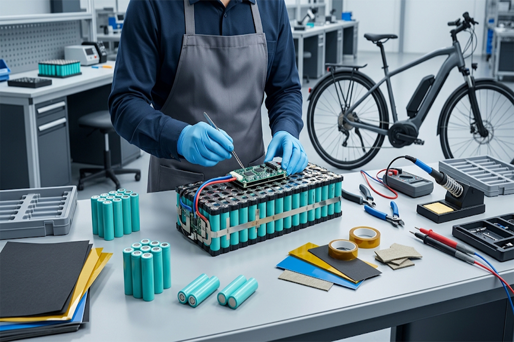
18650 lithium-ion cells have been used in many rechargeable battery packs for years, including portable electronics, power equipment, and electric mobility products. Their compact cylindrical format makes them useful when a battery pack needs a combination of energy, current output, and flexible mechanical design.
For e-bike battery pack manufacturers, however, choosing 18650 cells is not simply a matter of selecting the highest capacity available. The motor, controller, riding conditions, required range, charging system, enclosure, and BMS all affect the final cell specification.
A battery pack designed for a low-power city e-bike may have very different requirements from one designed for a higher-power electric bicycle used on hills or carrying heavier loads.
This guide explains how 18650 cells can be evaluated for e-bike battery packs, with a focus on OEM development, wholesale sourcing, and practical pack design.
Why 18650 Cells Are Used in E-Bike Battery Packs
An e-bike battery needs to store enough energy for the expected riding distance while remaining reasonably compact and manageable in weight.
18650 cells offer several characteristics that make them useful for custom battery packs:
- Standard cylindrical format
- Multiple capacity options
- Different discharge capabilities
- Flexible series-parallel configurations
- Established battery pack manufacturing processes
- Compatibility with spot-welding assembly
- Availability from different cell manufacturers
The cylindrical structure also allows manufacturers to arrange cells in different layouts according to the available enclosure.
For an OEM project, this flexibility can be useful when the battery housing has a fixed length, width, or height.
However, the cell itself is only one part of the battery system. A reliable e-bike pack also depends on cell matching, BMS design, interconnections, insulation, charging, enclosure construction, and thermal management.
What 18650 Battery Specifications Matter for an E-Bike?
Several specifications should be reviewed before selecting a cell.
The main ones are:
- Nominal voltage
- Maximum charging voltage
- Capacity
- Continuous discharge current
- Internal resistance
- Cell dimensions
- Cycle life
- Operating temperature
- Cell consistency
- Required certifications and documentation
Capacity determines how much energy the battery can store. Discharge capability determines how well it can support the motor and controller under load.
This is similar to the difference discussed in our article about high-capacity vs high-discharge 18650 batteries.
An e-bike pack normally needs a balance between the two rather than maximizing only one specification.

Understanding E-Bike Battery Voltage
Battery pack voltage is determined by the number of cells connected in series.
A common lithium-ion cell has a nominal voltage around 3.6V or 3.7V, while the fully charged voltage is typically around 4.2V.
For example:
| Configuration | Approx. Nominal Voltage | Approx. Full-Charge Voltage |
|---|---|---|
| 10S | 36V–37V | 42V |
| 13S | 46.8V–48.1V | 54.6V |
| 14S | 50.4V–51.8V | 58.8V |
These values are examples based on common lithium-ion cell ratings. The actual battery specification should follow the selected cell chemistry and the requirements of the e-bike system.
A 36V-class system and a 48V-class system should not be treated as interchangeable. The battery, charger, controller, display, and motor system need to be designed around the appropriate voltage range.
For a more detailed explanation, see 18650 battery voltage and charging limits.
How Many 18650 Cells Does an E-Bike Battery Need?
The answer depends on the required voltage and capacity.
The number of cells is determined by the series-parallel configuration.
For example:
10S2P = 20 cells
There are 10 cells in series and 2 cells in parallel in each series group.
Another example:
13S4P = 52 cells
There are 13 series groups, with 4 cells connected in parallel in each group.
The approximate pack capacity can be calculated as:
Pack capacity ≈ Cell capacity × Number of parallel cells
For a 3000mAh cell:
10S2P ≈ 3Ah × 2 = 6Ah
The nominal energy can then be estimated using:
Energy (Wh) ≈ Nominal voltage × Capacity (Ah)
So a nominal 36V-class, 6Ah pack would contain approximately:
36V × 6Ah = 216Wh
This is a simplified calculation. Real usable energy depends on the actual voltage curve, discharge current, cutoff settings, temperature, aging, and system efficiency.
For a broader explanation of energy calculations, see how much energy 18650 battery holds.

Capacity and E-Bike Range
Capacity is one of the specifications most closely associated with riding range.
A higher-capacity battery can store more energy, but the actual distance an e-bike can travel depends on many other factors.
These include:
- Motor power
- Controller settings
- Rider weight
- Cargo weight
- Riding speed
- Road surface
- Hills and gradients
- Wind
- Tire pressure
- Pedal assistance level
- Ambient temperature
- Riding style
For example, two e-bikes using batteries with the same nominal voltage and capacity may have noticeably different real-world range because their motors and riding conditions differ.
This is why an OEM battery supplier should avoid promising a specific riding distance based only on battery capacity.
The battery specification can define available electrical energy, while actual range is a system-level result.
High Capacity or High Discharge for an E-Bike?
This question depends heavily on the motor and controller.
A city e-bike with a relatively moderate current demand may place greater emphasis on energy capacity and runtime.
A higher-power e-bike may need cells capable of supporting stronger continuous and peak current.
| E-Bike Requirement | Cell Characteristic to Consider |
|---|---|
| Long riding time | Higher usable capacity |
| Strong acceleration | Higher discharge capability |
| Hill climbing | Continuous current capability |
| High controller current | Low internal resistance |
| Compact battery | Higher energy density |
| Frequent riding | Cycle-life performance |
| Cold-weather operation | Low-temperature performance |
The highest-capacity cell is therefore not automatically the best option.
Likewise, choosing an extremely high-discharge cell without considering energy requirements can result in a pack with less stored energy than the application needs.
The goal is to match the cell to the actual load profile.
Continuous and Peak Current
An e-bike motor does not necessarily draw the same current throughout a ride.
Current may increase during:
- Acceleration
- Hill climbing
- Carrying heavy loads
- Starting from a stop
- Riding against strong wind
- Operating at low speed under heavy torque demand
The controller may also impose a current limit.
For battery pack design, the supplier and OEM should therefore determine:
- Normal operating current
- Maximum controller current
- Expected peak current
- Peak duration
- Battery cutoff conditions
- BMS current limit
A simple estimate for a balanced parallel group is:
Cell current ≈ Pack current ÷ Number of parallel cells
For example, if the controller can demand 20A and the pack uses four cells in parallel:
20A ÷ 4 = 5A per cell
This is a simplified calculation and should not be used as the only basis for a commercial pack design. Current sharing can vary because of cell resistance, temperature, connection resistance, aging, and manufacturing tolerances.
The selected cell should have an appropriate continuous discharge rating with a suitable design margin.
Internal Resistance and Voltage Drop
Internal resistance becomes increasingly important as current increases.
A simplified relationship is:
Voltage drop = Current × Internal resistance
Suppose an individual cell has an internal resistance of 30mΩ and the current reaches 5A:
Voltage drop ≈ 5A × 0.03Ω = 0.15V
When multiple cells and connections are used, the complete pack has additional resistance from:
- Nickel strips
- Weld points
- Wires
- Connectors
- BMS MOSFETs
- Fuse components
- Other conductive parts
The motor may therefore experience a larger voltage drop than the individual cell specification suggests.
Low-resistance cells and well-designed current paths can help reduce this effect.
For high-current e-bike applications, it is useful to request actual resistance test data from the battery supplier rather than relying only on the cell’s capacity label.
Cell Matching in E-Bike Battery Pack
An e-bike battery pack can contain dozens of 18650 cells. Consistency between those cells becomes increasingly important as the number of cells increases.
Important matching parameters include:
- Capacity
- Internal resistance
- Open-circuit voltage
- State of charge
- Cell age
- Production batch
Cells with substantially different characteristics may not share current equally.
In a series-parallel pack, one weaker group can affect the performance of the entire battery. During charging, it may reach the upper voltage limit earlier. During discharge, it may reach the lower voltage limit earlier.
This can reduce usable pack capacity or cause the BMS to disconnect the pack before the other groups are fully utilized.
BMS Design for E-Bike Battery Packs
The BMS is an important part of an e-bike battery system.
Depending on the product design, the BMS may provide:
- Overcharge protection
- Over-discharge protection
- Overcurrent protection
- Short-circuit protection
- Temperature protection
- Cell balancing
- State-of-charge information
- Communication functions
The BMS current rating should be selected according to the actual battery and controller requirements.
For example, a battery intended for a controller with a high current limit should not be paired with a BMS whose protection threshold is below the normal operating range.
Some e-bike systems also use communication between the battery, controller, display, or charger. In such cases, the battery pack may need more than a basic protection board.
The BMS should therefore be considered during the early stages of battery pack development rather than added after the cells have already been selected.
Protected vs Unprotected 18650 Cells
Individual protected 18650 batteries are common in certain consumer applications, but a multi-cell e-bike battery pack normally uses a dedicated pack-level protection and management system.
A protected 18650 cell may contain a small protection circuit that adds length and changes the cell’s electrical behavior.
For a custom pack, using individual protected cells may create issues with:
- Pack dimensions
- Current capability
- Cell interconnection
- Weight
- Cost
- BMS coordination
For this reason, OEM manufacturers should determine whether the design calls for bare cells with a dedicated BMS or another specific cell architecture.
Our guide to protected vs unprotected 18650 batteries explains the differences in more detail.
Physical Dimensions and Battery Housing
Electrical specifications are only half of the design problem.
The cells must also fit the battery enclosure.
An 18650 cell has an approximate diameter of 18mm and length of 65mm, but actual dimensions vary slightly by model and construction.
The design should account for:
- Cell diameter tolerance
- Cell length
- Insulation
- Cell holder
- Nickel strips
- BMS
- Wiring
- Connectors
- Housing walls
- Thermal materials
- Assembly clearance
Protected cells can also be longer than standard unprotected cells.
A few millimeters can matter when designing a compact e-bike battery enclosure. For this reason, obtain a mechanical drawing or sample cells before finalizing the housing.
See 18650 battery dimensions and size tolerance for more information.
Flat-Top Cells and Battery Pack Assembly
Flat-top 18650 cells are commonly considered for welded battery pack construction because the terminal geometry can work well with cell interconnections.
However, terminal design should be selected according to the actual pack structure.
The manufacturer should verify:
- Positive terminal shape
- Negative terminal construction
- Insulation ring requirements
- Welding compatibility
- Cell spacing
- Nickel strip dimensions
- Current path design
The difference between flat-top and button-top cells is explained in flat-top vs button-top 18650 batteries.
For an OEM project, the supplier should receive the mechanical drawing and pack layout before confirming the final cell model.
Thermal Management
E-bike batteries may operate outdoors across a wide range of temperatures.
Heat can come from:
- Cell internal resistance
- High discharge current
- BMS components
- Welded connections
- Connectors
- External environmental conditions
High current can produce significant heat because resistive losses increase with the square of current.
A simplified relationship is:
Heat ≈ I² × R
This means that reducing resistance in the cell and current path can have a meaningful effect on thermal performance.
Thermal design may include:
- Appropriate cell spacing
- Temperature sensors
- Heat-conductive materials
- Suitable enclosure design
- Correct current-path sizing
- BMS thermal protection
- Operating temperature limits
The complete battery should be tested under representative riding and charging conditions.
Charging Requirements
The charger must match the battery pack’s voltage and charging profile.
For a conventional lithium-ion pack, the charger is normally selected according to the number of cells in series and the cell chemistry.
For example, a 10S lithium-ion pack commonly uses a charger designed around a 42V full-charge voltage.
A 13S pack commonly uses a charger designed around 54.6V full-charge voltage.
These are examples for common lithium-ion configurations, not universal specifications for every 18650 cell.
The charger should be compatible with:
- Battery series count
- Cell chemistry
- Maximum charge voltage
- Required charging current
- BMS
- Connector
- Communication requirements, if applicable
Charging should never be specified solely from the nominal battery voltage.
Cycle Life and E-Bike Usage
An e-bike battery may be charged frequently, particularly when the vehicle is used for commuting or commercial delivery.
Cycle life depends on several factors:
- Depth of discharge
- Charge current
- Discharge current
- Operating temperature
- Charging voltage
- Storage conditions
- Cell quality
- Pack balance
- BMS settings
A supplier’s cycle-life figure should always be reviewed together with its test conditions.
For example, a cycle-life result obtained at a moderate current and controlled temperature may not represent performance in a high-current e-bike application.
OEM buyers should request the test conditions before comparing cycle-life numbers from different cell suppliers.
Safety and Quality Considerations
An e-bike battery is a high-energy rechargeable system, so cell quality and pack manufacturing control are important.
The production process should include appropriate inspection and testing, such as:
- Cell voltage testing
- Capacity testing
- Internal resistance testing
- Cell matching
- Weld inspection
- Insulation inspection
- BMS functional testing
- Pack voltage testing
- Charge and discharge testing
- Temperature testing
Depending on the destination market and transport requirements, documentation such as UN38.3, MSDS, CE, RoHS, or other applicable compliance documents may be required.
The exact requirements depend on the product, destination, transport method, and applicable regulations.
What OEM Buyers Should Provide to the Supplier
A battery supplier can provide a more accurate recommendation when the buyer supplies actual application information.
A useful RFQ should include:
Electrical requirements
- Nominal voltage
- Maximum voltage
- Required capacity
- Motor power
- Controller current
- Expected peak current
- Charging current
Mechanical requirements
- Maximum battery dimensions
- Housing drawing
- Cell orientation
- Connector type
- Installation method
Environmental requirements
- Operating temperature
- Storage temperature
- Water or dust exposure
- Vibration requirements
Commercial requirements
- Sample quantity
- Expected annual volume
- Target production schedule
- Required certifications
- Destination market
For a custom battery pack, a drawing and sample housing can significantly reduce misunderstandings during development.
Common Mistakes When Selecting 18650 Cells for E-Bikes
Choosing Capacity Without Checking Current
A large mAh number does not automatically mean the cell can support the required motor current.
Designing the Pack Around Nominal Voltage Only
The full-charge voltage must also match the charger, BMS, and controller.
Ignoring Cell Matching
A pack made from poorly matched cells may have reduced usable capacity and inconsistent performance.
Using the Wrong BMS
The BMS current and protection settings need to correspond with the actual system.
Forgetting the Enclosure
Cell dimensions, insulation, BMS placement, and wiring all consume space.
Comparing Datasheets Without Test Conditions
Capacity, resistance, and cycle-life numbers should be compared under equivalent test conditions.
Testing Only Individual Cells
A cell can perform well by itself while the completed pack has problems caused by welding, BMS resistance, wiring, thermal conditions, or cell imbalance.

A Practical Selection Checklist
Before approving an 18650 cell for an e-bike battery pack, confirm:
- Cell chemistry
- Nominal voltage
- Maximum charge voltage
- Rated capacity
- Continuous discharge current
- Peak current requirement
- Internal resistance
- Cell dimensions
- Terminal type
- Cell matching method
- BMS specification
- Charger compatibility
- Temperature range
- Cycle-life test conditions
- Required certifications
- Sample test results
- Pack-level test results
This checklist can be used as a starting point for an OEM battery RFQ.
Conclusion
18650 lithium-ion cells can be a practical option for e-bike battery pack manufacturing when the cell and pack are correctly matched to the application.
The main selection factors are not limited to capacity. Voltage, continuous discharge current, peak current, internal resistance, cell matching, BMS design, thermal management, mechanical dimensions, and charging requirements all affect the final battery pack.
For moderate-power e-bikes, a higher-capacity cell may help increase stored energy and runtime. For applications with higher current demand, a suitable high-discharge cell may be more appropriate. In both cases, the complete pack should be evaluated rather than judging the cell from one specification.
For OEM and wholesale projects, provide the motor and controller requirements, desired voltage and capacity, maximum dimensions, BMS requirements, and application environment when requesting samples. This gives the battery manufacturer enough information to recommend and test a suitable 18650 cell configuration.
For standard cells and custom battery pack sourcing, explore our 18650 lithium battery cells.
-

12V 4400 mah Lithium ion 3S2P 18650 Battery Pack
-

18650 2000mAh 3.7 volt Lithium-ion Battery
-

18650 20V 3.0Ah Cordless Drill battery
-

18650 22.2V 7.8Ah 2600Mah 6S3P Rechargeable Battery Pack
-

18650 2600mAh Rechargeable Lithium-Ion Battery 3.7V
-

18650 3.7V 10Ah Li-Ion Power Battery Pack
-

18650 3.7V 3300mah Rechargeable Lithium ion Battery
-

18650 7S7P 24V 14Ah Lithium ion Electric Scooter Battery Pack
-

18650 battery 3.7V 1500mAh Lithium-Ion Battery
-

18650 Battery 3500 mah Rechargeable Battery Cells
-

18650 Electric Scooter 48V 13000mAh Lithium Battery
-

2600mAh 3S1P 11.1V 18650 Battery Packs
-

3.7V Li ion Rechargeable 3000mah 18650 Battery Cell
-

36V 5200mAh 10S2P 18650 Battery Pack
-

48v 4400mah 13S2P 18650 Rechargeable Battery Pack
-

7S2P 24V 18650 Lithium Battery Pack
-

Electric Scooter 36V 4400mAH 10S2P 18650 Battery Pack
-

ICR 18650 Battery 2200mah 3.7V
Leave a Reply