
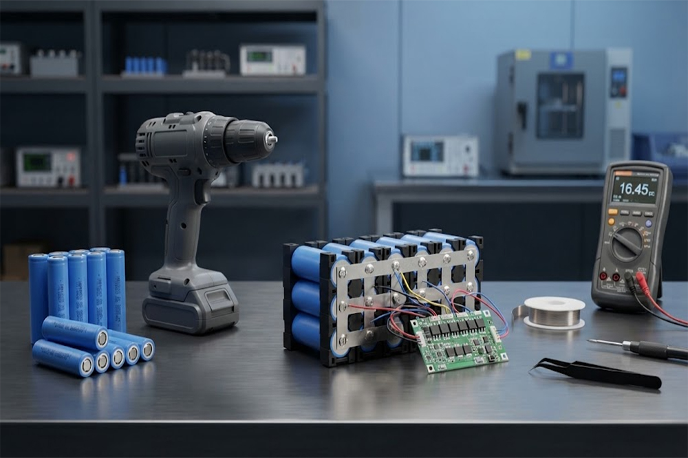
Standard 18650 lithium-ion battery cells are widely used in portable electronics, flashlights, industrial equipment, and custom battery packs. They are also found in many cordless power tool batteries. However, not every 18650 cell is suitable for a drill, impact driver, saw, or other high-current equipment.
Power tools place different demands on a battery than low-power electronics. Motor startup can create a sudden current surge, while continuous operation may generate substantial heat inside the cells, connections, and protection system.
The key question is not simply whether an 18650 battery can fit inside a power tool pack. The more important question is whether the cell can safely and reliably provide the required voltage, continuous current, peak current, runtime, and cycle life.
This guide explains what buyers, engineers, and OEM battery pack manufacturers should check before using standard 18650 cells in power tool applications.
Why Power Tools Require Special Battery Consideration
A cordless power tool may appear simple from the outside, but its battery system must support several changing conditions.
During operation, the motor may require:
- A high current when starting
- Short bursts of additional power
- Continuous current while cutting, drilling, or driving
- Stable voltage as the battery discharges
- Repeated charge and discharge cycles
- Resistance to vibration and mechanical movement
- Reliable protection against overcurrent and overheating
The current demand is not always constant. A drill working without resistance may draw relatively little current, while drilling into hard material can cause the current to rise quickly.
This changing load makes cell selection especially important. A battery with a high capacity rating may not perform well if it cannot maintain the required current under load.
Can Any Standard 18650 Battery Be Used in a Power Tool?
No. The term “standard 18650” mainly describes the cell’s approximate physical format. It does not guarantee a particular current rating or application suitability.
An 18650 cell generally has an approximate diameter of 18mm and a length of 65mm, but cells with the same size can have very different electrical characteristics.
Two cells may both be labeled 3000mAh while having different:
- Continuous discharge ratings
- Internal resistance
- Voltage curves
- Temperature limits
- Cycle-life performance
- Recommended applications
- Manufacturing quality
A high-capacity cell designed for moderate current should not automatically be used in a power tool. Power tools often require cells designed for stronger discharge performance.
For more information about the standard format, see the guide to what standard 18650 batteries are.

High-Capacity vs High-Discharge Cells for Power Tools
Power tool battery packs generally need a balance between energy storage and power output.
A high-capacity cell can provide longer runtime under moderate loads. A high-discharge cell is usually designed to deliver more current with lower voltage sag and better thermal performance under demanding conditions.
| Requirement | High-Capacity Cell | High-Discharge Cell |
|---|---|---|
| Main advantage | Longer runtime | Stronger current delivery |
| Heavy motor load | May be limited by current rating | Usually more suitable |
| Voltage sag | May be more noticeable | Usually better controlled |
| Heat under high current | Can be higher | Often lower under comparable conditions |
| Runtime at light load | Often favorable | Depends on capacity |
| Typical use | Moderate-current equipment | Power tools and high-current devices |
This does not mean every high-discharge cell is suitable for every power tool. The cell’s actual specifications must be compared with the tool’s electrical requirements.
For a detailed comparison, read high-capacity vs high-discharge 18650 batteries.
Check the Tool’s Voltage Requirement
The first electrical specification to confirm is the battery pack voltage.
Common power tool battery systems may use several cells connected in series. For example:
- 3S pack: approximately 10.8V or 11.1V nominal
- 4S pack: approximately 14.4V or 14.8V nominal
- 5S pack: approximately 18V or 18.5V nominal
- 6S pack: approximately 21.6V or 22.2V nominal
The exact nominal voltage depends on the cell chemistry and the manufacturer’s labeling method. A lithium-ion cell is commonly rated around 3.6V or 3.7V nominal, with a full-charge voltage of approximately 4.2V.
For example, a 5S lithium-ion pack may have:
- Nominal voltage: approximately 18V to 18.5V
- Full-charge voltage: approximately 21V
The tool, charger, BMS, and battery pack must be designed for the same voltage range. Using an incompatible voltage can damage the tool or create a serious safety risk.
Review the explanation of 18650 battery voltage and charging limits before selecting the series configuration.
Continuous Discharge Current Matters
The continuous discharge current is one of the most important specifications for power tool battery packs.
A tool may draw a moderate current during normal operation but require much more current when:
- The motor starts
- The bit becomes stuck
- The blade meets resistance
- The tool is used at low speed
- The user applies heavy pressure
- The battery is nearly discharged
The selected cell should be able to support the expected continuous load without excessive heat or voltage drop.
For example, if a pack contains several cells in parallel, the load current is shared between the cells. However, the actual current distribution depends on:
- Cell resistance
- Cell matching
- Nickel strip design
- Welding quality
- Wiring resistance
- BMS resistance
- Temperature
- State of charge
A simple theoretical estimate for a balanced parallel group is:
Current per cell ≈ Total pack current ÷ Number of parallel cells
This is only an initial estimate. The real design should include current imbalance, temperature rise, aging, and safety margins.
Peak Current During Motor Startup
Power tools often have a high starting current. The motor needs additional energy to begin rotating, and the current may increase further when the tool encounters resistance.
This is why a cell’s peak-current specification may be relevant. However, buyers should be careful when interpreting this value.
A supplier may specify a pulse current for:
- A few seconds
- A specific temperature
- A defined state of charge
- A particular rest interval
- A specified cutoff voltage
A short-duration pulse rating should not be treated as a continuous discharge rating.
When evaluating a power tool battery cell, request both:
- The recommended continuous discharge current
- The tested peak or pulse current and its exact conditions
The actual motor controller may also limit current electronically, so the cell should be selected based on the complete tool system rather than the motor label alone.
Internal Resistance and Voltage Sag
Internal resistance has a direct effect on power tool performance.
When a tool draws a high current, the cell voltage may drop. If the voltage falls below the tool’s operating threshold, the tool may slow down, stop, or trigger a protection function.
The simplified relationship is:
Voltage drop ≈ Current × Internal resistance
A cell with lower internal resistance usually produces less voltage sag under the same load. It may also generate less internal heat.
Voltage sag can become more noticeable when:
- The battery is cold
- The state of charge is low
- The cells are aged
- The load current is high
- The pack contains poor-quality connections
- The cells are not properly matched
For this reason, a battery pack should be tested under real operating conditions rather than evaluated only by nominal capacity.
Capacity Affects Runtime, Not Just the Label
Battery capacity is usually expressed in mAh or Ah. A higher capacity may provide longer runtime, but actual runtime depends on the tool’s load.
A 2500mAh high-discharge cell may be more suitable for a demanding power tool than a 3500mAh cell designed for moderate current.
When comparing capacity, check:
- Rated discharge current
- Test temperature
- Discharge cutoff voltage
- Capacity retention after cycling
- Capacity at the intended current
- Actual operating load
The capacity rating is normally measured under a specified test condition. It may not represent the same available energy when the cell is discharged at a high current.
See the guide to standard 18650 battery capacity for a closer look at common capacity ratings.
Choosing the Right Series and Parallel Configuration
The pack configuration determines the voltage and current capability.

Series Connection
Cells connected in series increase the pack voltage. The capacity in Ah remains approximately the same as one cell group.
For example:
- 5S1P uses five cells in series
- Nominal voltage increases
- The current rating is still limited by the individual cell
Parallel Connection
Cells connected in parallel increase capacity and can increase the available current.
For example:
- 5S2P uses five series groups with two cells in parallel in each group
- The pack contains 10 cells
- Capacity is approximately doubled compared with a 5S1P pack
- Current capability may increase when the cells and connections are properly matched
The number of cells should not be selected only from the desired voltage. The pack designer must also calculate:
- Continuous current
- Peak current
- Runtime
- Cell temperature
- BMS current limit
- Wire and connector rating
- Nickel strip size
- Available enclosure space
The planned series-parallel arrangement should be validated through electrical and thermal testing.
Cell Matching Is Important in Power Tool Packs
A power tool battery pack normally contains multiple cells. These cells should have compatible electrical characteristics.
Important matching parameters include:
- Capacity
- Internal resistance
- Open-circuit voltage
- State of charge
- Cell age
- Manufacturing batch
- Discharge performance
Poorly matched cells may cause uneven current sharing. One cell or parallel group may become hotter or reach its voltage limit earlier than others.
For series-connected groups, imbalance can also cause the BMS to cut off charging or discharging earlier than expected.
BMS and Protection Design
A power tool battery pack should include a suitable battery management or protection system.
Depending on the design, the BMS may provide:
- Overcharge protection
- Over-discharge protection
- Overcurrent protection
- Short-circuit protection
- Temperature monitoring
- Cell balancing
- Communication with the tool or charger
The BMS current rating should match the actual load. A BMS with a current limit below the tool’s normal operating requirement may cause unwanted shutdowns.
Some commercial power tool packs also include identification, communication, fuel-gauge, or authentication functions. These features may be required for compatibility with the original tool and charger.
A simple protection board may not be enough for a professional power tool pack. The electrical interface and communication requirements should be confirmed before development.
Mechanical Design Is Also Important
Power tools generate vibration, impact, and repeated movement. A battery pack must be mechanically stable as well as electrically reliable.
The pack design should consider:
- Cell holders or structural supports
- Insulation between cells
- Nickel strip welding
- Vibration resistance
- Shock protection
- Connector retention
- Enclosure fit
- Heat dissipation
- Moisture and dust exposure
- Serviceability
Cells should not be allowed to move freely inside the housing. Movement can damage insulation, weld points, wires, or the cell casing.
The physical size of the cell is also important. Protected 18650 cells may be longer than standard unprotected cells, which can affect enclosure compatibility. Review 18650 battery dimensions and size tolerance before finalizing the pack layout.

Flat-Top or Button-Top Cells?
Power tool battery packs normally use a specific terminal and interconnection design. The cell terminal shape must match the pack’s mechanical and electrical construction.
Flat-top cells are common in many custom battery packs because they can be arranged and welded efficiently. Button-top cells may be required for certain holders or equipment designs, but they may add length and affect contact geometry.
The correct terminal type depends on:
- Pack structure
- Cell holder design
- Welding method
- Contact arrangement
- Insulation design
- Available space
For a detailed comparison, see flat-top vs button-top 18650 batteries.
Thermal Management and Temperature Testing
High-current discharge creates heat. Power tool packs should be evaluated under realistic operating conditions, including heavy loads and repeated cycles.
Temperature testing should consider:
- Cell surface temperature
- Temperature differences between cells
- BMS temperature
- Nickel strip temperature
- Connector temperature
- Enclosure temperature
- Ambient temperature
- Charging temperature
A pack that performs well during a short laboratory test may behave differently during repeated drilling, cutting, or impact operation.
Thermal performance can be improved through:
- Selecting lower-resistance cells
- Using suitable cell spacing
- Improving current paths
- Reducing connector resistance
- Adding temperature sensors
- Designing appropriate ventilation or heat transfer
- Setting suitable protection limits
The cell manufacturer’s maximum operating temperature should always be respected.
Cycle Life Under Power Tool Loads
Power tools may be used frequently and discharged at relatively high current. Cycle life should therefore be evaluated under conditions similar to the final application.
Cycle life depends on:
- Discharge current
- Charge current
- Depth of discharge
- Operating temperature
- Charging voltage
- Rest periods
- Cell chemistry
- Mechanical conditions
- Protection settings
A cell’s cycle-life claim is only meaningful when the test conditions are known. Ask the supplier for the test method, capacity-retention target, and current used during testing.
For a commercial product, the pack should be tested over repeated charge and discharge cycles rather than relying only on a single capacity test.
What OEM Buyers Should Ask a Battery Supplier
Before placing a power tool battery order, request the following information:
Electrical Specifications
- Nominal voltage
- Maximum charge voltage
- Rated capacity
- Recommended continuous discharge current
- Maximum pulse current
- Internal resistance
- Discharge cutoff voltage
- Operating temperature range
Mechanical Specifications
- Cell diameter
- Cell length
- Flat-top or button-top terminal
- Cell weight
- Insulation dimensions
- Welding compatibility
- Pack dimensions
- Connector and housing requirements
Quality and Compliance Documents
- UN38.3 test summary
- MSDS
- Applicable transport documents
- CE or RoHS documentation where required
- Quality inspection records
- Capacity test results
- Resistance test results
- Batch traceability information
Pack-Level Requirements
- BMS current rating
- Cell balancing method
- Temperature protection
- Charger compatibility
- Communication requirements
- Sample testing procedure
- Warranty and quality agreement
A reliable supplier should be able to explain not only the cell’s nominal specifications but also how the cell performs in the proposed pack configuration.
Common Mistakes to Avoid
Selecting Cells by Capacity Alone
A high mAh value does not guarantee suitable current performance.
Treating Peak Current as Continuous Current
A short pulse rating cannot replace a continuous discharge specification.
Ignoring the BMS Current Limit
The BMS must support the actual tool load and startup behavior.
Using Unmatched Cells
Differences in capacity and resistance can create uneven current sharing and early pack cutoff.
Forgetting Mechanical Stress
Vibration and impact can damage a poorly supported battery pack.
Testing Only at Room Temperature
Power tools may be used in cold workshops, hot environments, or enclosed spaces. Temperature testing should reflect the actual application.
Copying an Existing Pack Without Verification
A similar-looking pack may use a different cell chemistry, BMS, communication system, or current rating.
Conclusion
Standard 18650 batteries can be used in power tool battery packs, but only when the selected cells meet the electrical, thermal, mechanical, and protection requirements of the application.
The most important factors include voltage, continuous discharge current, peak current, internal resistance, capacity, cell matching, BMS design, and thermal management. High-discharge cells are often more suitable for demanding motor loads, while high-capacity cells may be useful when runtime is the main priority and current demand is moderate.
For OEM and wholesale projects, the safest approach is to confirm the tool’s load profile, design the series-parallel configuration, test sample cells, and validate the complete battery pack before mass production.
Explore our 18650 lithium battery cells for standard cell sourcing and custom battery pack development.
-

12V 4400 mah Lithium ion 3S2P 18650 Battery Pack
-

18650 2000mAh 3.7 volt Lithium-ion Battery
-

18650 20V 3.0Ah Cordless Drill battery
-

18650 22.2V 7.8Ah 2600Mah 6S3P Rechargeable Battery Pack
-

18650 2600mAh Rechargeable Lithium-Ion Battery 3.7V
-

18650 3.7V 10Ah Li-Ion Power Battery Pack
-

18650 3.7V 3300mah Rechargeable Lithium ion Battery
-

18650 7S7P 24V 14Ah Lithium ion Electric Scooter Battery Pack
-

18650 battery 3.7V 1500mAh Lithium-Ion Battery
-

18650 Battery 3500 mah Rechargeable Battery Cells
-

18650 Electric Scooter 48V 13000mAh Lithium Battery
-

2600mAh 3S1P 11.1V 18650 Battery Packs
-

3.7V Li ion Rechargeable 3000mah 18650 Battery Cell
-

36V 5200mAh 10S2P 18650 Battery Pack
-

48v 4400mah 13S2P 18650 Rechargeable Battery Pack
-

7S2P 24V 18650 Lithium Battery Pack
-

Electric Scooter 36V 4400mAH 10S2P 18650 Battery Pack
-

ICR 18650 Battery 2200mah 3.7V
Leave a Reply