
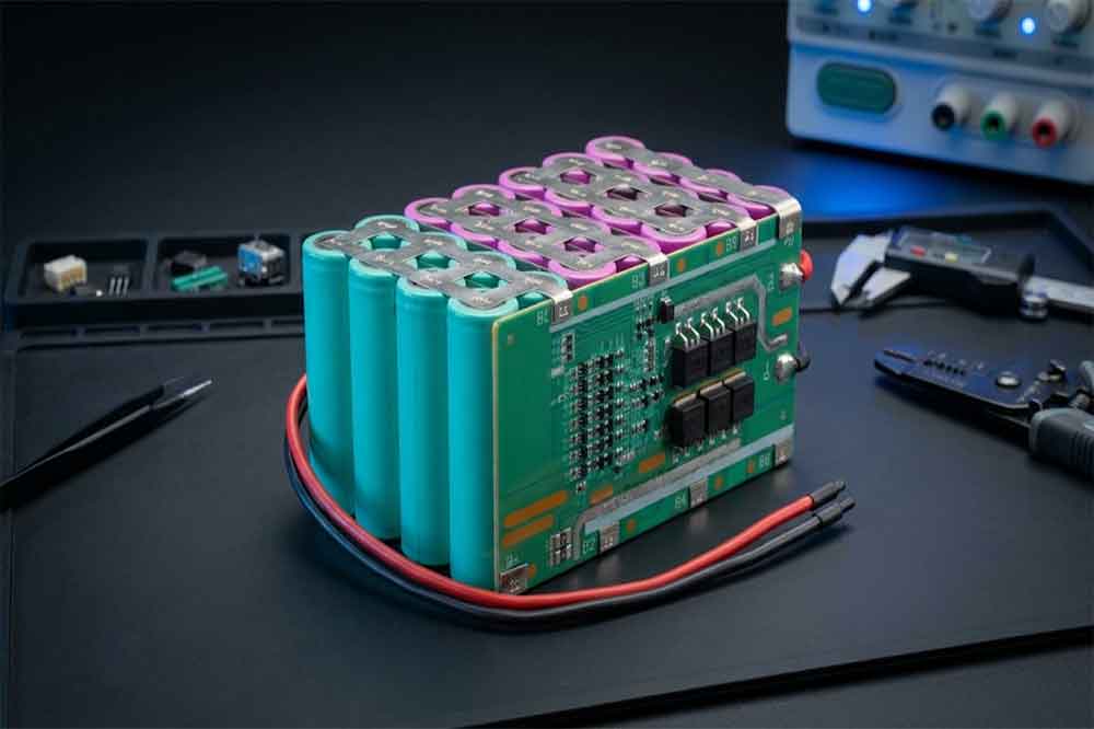
Developing a battery pack for an OEM product is not simply a matter of putting several 18650 cells together and adding a protection board. The battery has to fit the equipment, deliver the required power, work with the charging system, and remain reliable under the conditions in which the final product will operate.
For an equipment manufacturer, a battery pack that performs well on a laboratory test bench may still create problems after installation. The connector may not match the device, the pack may be slightly too large for the housing, or the protection circuit may interrupt power during startup.
These details are worth addressing before production begins.
A protected 18650 battery pack combines rechargeable lithium-ion cells with an electrical protection system. For OEM applications, its design should be based on the actual equipment requirements rather than a standard battery configuration selected without considering the application.
Explore our [18650 lithium battery solutions] for different OEM and industrial applications, including battery cell selection and customized battery pack development.
Why OEM Projects Need a Protected 18650 Battery Pack
18650 lithium-ion cells are widely used in industrial instruments, portable equipment, backup power systems, security devices, and various electronic products.
Their cylindrical structure makes them relatively easy to arrange into different battery configurations. Manufacturers can also combine cells in series and parallel to achieve different voltage and capacity requirements.
However, individual 18650 cells do not automatically provide all the protection required by the finished equipment.
A protection circuit helps manage operating conditions such as excessive charging voltage, excessive discharge, overcurrent, and short circuits. Depending on the application, additional temperature monitoring and communication functions may also be necessary.
For OEM buyers, the advantage of a properly designed protected battery pack is that the power system can be developed around the equipment instead of forcing the equipment manufacturer to adapt its design around an unsuitable standard battery.
Step 1: Define the Electrical Requirements
Before selecting cells, the engineering team needs a clear understanding of how the battery will be used.
The first step is to collect the electrical parameters of the equipment.
Voltage and Capacity
Start with the operating voltage required by the device.
For example, a product designed for a nominal 7.2V lithium-ion battery may require a 2S configuration. A higher-voltage application may need additional cells connected in series.
Capacity determines how much energy the battery can store and how long the equipment can operate between charges.
A portable instrument used occasionally may have different capacity requirements from a continuously operating monitoring device.
It is important to distinguish between nominal voltage, fully charged voltage, and the device’s actual operating voltage range. The battery and equipment must be compatible throughout the complete operating cycle.
Continuous and Peak Discharge Current
Capacity alone does not determine whether a battery is suitable.
An electric motor, wireless transmitter, pump, or other power-consuming component may require a temporary current increase during startup.
For this reason, OEM specifications should include:
- Continuous discharge current.
- Peak discharge current.
- Peak current duration.
- Normal operating load.
- Startup or transient current.
The selected cells and protection circuit must both support the required current. A protection board with an unsuitable current rating may disconnect the battery even when the cells themselves can supply the load.
Charging Requirements
The charging method must also be defined early.
Confirm the charging voltage, charging current, charging connector, and whether the equipment uses an external charger or an integrated charging circuit.
For a lithium-ion battery pack, the charger must be compatible with the series configuration and the cell chemistry.
Step 2: Select the Right 18650 Cells
Cell selection has a direct influence on battery capacity, operating time, size, weight, and service life.
Not every 18650 cell is suitable for every OEM project.
Cell Chemistry and Capacity
Common lithium-ion cell chemistries include NMC, NCA, and LCO, while LiFePO4 is another lithium battery chemistry with different voltage characteristics.
The choice depends on the application’s energy density, operating voltage, discharge requirements, temperature conditions, and expected cycle life.
For a compact portable device, higher energy density may be important. For equipment with a relatively high power demand, discharge capability may deserve more attention than maximum capacity.
The engineering team should evaluate the actual cell datasheet rather than relying only on the capacity printed on the cell.
Discharge Performance and Cell Consistency
The selected cells should have sufficient discharge capability for the equipment’s normal and peak loads.
Cell consistency is equally important.
When multiple cells are connected in one battery pack, differences in capacity, internal resistance, and state of charge can affect pack performance. A suitable cell-matching and incoming inspection process helps reduce these differences.
For OEM production, the cell supplier, model, specifications, and production batches should be controlled as part of the material management process.
Matching Cells for Pack Assembly
Using different cell models or mixing cells with significantly different histories is not a good approach for a new battery pack.
The cells should be checked for appearance, voltage, capacity, and internal resistance according to the manufacturer’s quality requirements.
This is particularly important for packs containing several series-connected cell groups.
Step 3: Determine the Battery Pack Configuration
The number of cells and their connection method determine the battery’s voltage and capacity.
Series connections increase voltage, while parallel connections increase capacity and current capability.

For example:
- 1S1P: One cell in series and one parallel path.
- 2S1P: Two cells connected in series.
- 2S2P: Two series groups, each containing two parallel cells.
- 3S2P: Three series groups with two parallel cells per group.
- 4S2P: Four series groups with two parallel cells per group.
A 2S2P pack contains four cells. Its nominal voltage is approximately twice that of one cell, while its capacity is approximately twice the capacity of one cell, assuming identical cells.
The actual voltage and usable capacity depend on the cell specifications and operating limits.
Choosing the Right Pack Structure
The best configuration is not necessarily the one with the highest capacity.
For OEM equipment, engineers must consider the available installation space, weight restrictions, required runtime, and electrical load.
A 3S1P arrangement may fit a narrow enclosure better than a larger parallel configuration. In another project, a 2S2P arrangement may provide the required capacity without exceeding the device’s voltage limit.
The battery layout should therefore be evaluated together with the equipment’s mechanical drawings.
Step 4: Design the Protection System
A protected 18650 battery pack needs a protection system matched to its electrical configuration and application.
This may use a protection circuit module (PCM) or a more advanced battery management system (BMS), depending on the project.
Overcharge and Over-Discharge Protection
Overcharge protection helps prevent individual cells or series groups from exceeding their specified charging voltage.
Over-discharge protection disconnects the load when the battery reaches its defined lower voltage limit.
For a multi-series pack, cell-level voltage monitoring and balancing requirements should be considered.
Overcurrent and Short-Circuit Protection
The protection circuit should respond appropriately when the battery experiences excessive current or a short circuit.
The selected current thresholds must be compatible with the normal load and peak current requirements.
Setting the protection threshold too low may cause unwanted shutdowns. Setting it too high may fail to provide the intended protection.
Temperature Monitoring and BMS Functions
Temperature monitoring is useful when the battery operates in environments with changing temperatures or under relatively heavy loads.
An NTC temperature sensor can monitor cell or pack temperature and provide protection against abnormal thermal conditions.
Some OEM applications also require additional functions, such as:
- Cell voltage monitoring.
- Battery balancing.
- State-of-charge estimation.
- Remaining capacity reporting.
- Communication through SMBus, UART, or CAN, where supported by the selected system.
Not every project needs an advanced BMS. The protection system should be selected according to the equipment’s actual requirements, not simply because more functions appear attractive.

Step 5: Design the Physical Structure
A battery pack can meet every electrical specification and still fail to fit the final product.
Mechanical design should therefore be treated as an important part of OEM battery development.
Dimensions and Cell Arrangement
The engineering team needs to consider the cell diameter, cell length, insulation thickness, connection structure, protection board, wiring, and enclosure.
The finished pack dimensions are usually larger than the combined dimensions of the bare cells.
For example, a 2S2P arrangement may require a rectangular layout, while another application may need a long, narrow structure.
Before confirming the design, check the complete installation space, including cable exit positions and connector clearance.
Connectors, Wires, and Enclosure
Connector type and wire specifications should match the equipment.
Important details include connector model, polarity, wire length, wire gauge, and current rating.
OEM projects may also require customized PVC wrapping, plastic housings, mounting brackets, labels, and product identification.
These details should be confirmed before prototype production. Changing a connector or wire position after the enclosure has been finalized can create unnecessary development work.
Insulation and Mechanical Protection
Insulation materials and mechanical support help protect the cells and electrical connections.
The design should prevent unintended contact between conductive components and reduce the possibility of damage caused by vibration, movement, or assembly pressure.
Nickel strips, insulation rings, fish paper, protective sleeves, and suitable cell holders may be used according to the pack design.
The final structure must not apply excessive pressure to cylindrical cells or interfere with their safety features.
Step 6: Prototype and Test the Battery Pack
A prototype is an important step before committing to mass production.
It gives the OEM customer and battery manufacturer an opportunity to identify problems that may not be obvious from drawings or electrical calculations.
Electrical Performance Testing
Typical checks include:
- Pack voltage and polarity.
- Charging and discharging performance.
- Actual capacity.
- Continuous discharge capability.
- Voltage drop under load.
- Temperature rise during operation.
Testing should use conditions that reflect the equipment’s real operating profile.
Protection Function Verification
Protection functions should be verified using controlled test procedures and appropriate equipment.
The engineering team should confirm that the protection system responds correctly to relevant abnormal conditions, including overcharge, over-discharge, overcurrent, and short circuit, as applicable to the design.
These tests should follow the applicable cell, BMS, and battery-pack specifications. They should not be improvised on an assembled battery pack.
Environmental and Mechanical Checks
Depending on the application, additional validation may include vibration, temperature cycling, storage, and mechanical installation checks.
For industrial equipment, the battery may be exposed to repeated movement or long operating periods. A prototype should be evaluated under realistic conditions rather than only being checked for whether it powers on.

Step 7: Prepare for OEM Mass Production
After the prototype is approved, the next stage is production preparation.
The manufacturer should establish a controlled specification covering cell model, cell configuration, protection board, wiring, connectors, enclosure, labeling, and finished dimensions.
A production sample should be retained as a reference for subsequent orders.
Incoming material inspection, assembly controls, welding quality checks, electrical testing, and finished-product inspection should be included in the production process.
OEM buyers should also confirm the required certifications and transportation documentation before placing a production order. Requirements may vary depending on battery design, destination market, and transportation method.
For lithium battery shipments, UN38.3 test requirements and the applicable shipping documentation should be reviewed.
A reliable production process is not just about assembling the same number of cells every time. It is about making sure that each batch follows the approved design and passes the required quality checks.
Common Mistakes in OEM 18650 Battery Pack Development
Several problems appear repeatedly during battery pack development.
Selecting cells based only on capacity: A high-capacity cell may not provide the discharge performance required by the equipment.
Ignoring peak current: The battery may work under normal conditions but shut down when the device starts.
Choosing the BMS too late: Protection board dimensions and wiring can affect the entire mechanical layout.
Confirming dimensions without the connector: The battery may fit inside the housing, but the connector or cable may not have enough clearance.
Skipping prototype validation: Problems discovered after mass production are usually more expensive to correct.
Changing components without revalidation: Replacing a cell or protection board with a different model may affect the pack’s electrical and safety characteristics.
A good OEM development process identifies these issues before the first production order.
Final Considerations
Building a protected 18650 battery pack for an OEM application requires coordination between electrical design, cell selection, protection circuit development, mechanical engineering, and production quality control.
The most suitable battery pack is not necessarily the one with the largest capacity or the most advanced BMS. It is the one that meets the equipment’s voltage, current, runtime, size, and operating requirements while maintaining a consistent production standard.
For equipment manufacturers planning a new product, sharing the electrical specifications and installation drawings with an experienced battery pack manufacturer at an early stage can make the development process more efficient.
Apsenx supports OEM and ODM lithium battery pack projects, including cell selection, series-parallel configuration, protection circuit matching, connector selection, customized dimensions, and battery pack assembly.
Frequently Asked Questions
1. Can a protected 18650 battery pack be customized for OEM applications?
Yes. OEM battery packs can be customized in voltage, capacity, cell arrangement, dimensions, connectors, protection functions, enclosure, and labeling, subject to technical feasibility.
2. How do I choose the right 18650 cells for an OEM battery pack?
Start with the required voltage, capacity, continuous and peak discharge current, operating temperature, and available installation space. Then select cells with suitable specifications and consistent performance.
3. Does every protected 18650 battery pack need a BMS?
Every pack needs an appropriate protection strategy. Depending on its configuration and application, this may use a PCM or a more advanced BMS with additional monitoring and balancing functions.
4. How long does OEM 18650 battery pack development take?
The timeline depends on cell availability, design complexity, protection circuit requirements, and prototype testing. A straightforward project may move faster than one requiring custom electronics, enclosure development, or communication functions.
5. What information should I provide when requesting an OEM battery pack quotation?
Provide the required voltage, capacity, discharge current, charging specifications, pack dimensions, connector details, operating environment, estimated order quantity, and any required certifications. A product drawing or existing battery sample is also helpful.
Related Article
For a closer look at the electrical safety functions behind this design, read our guide to [how protection is designed in a protected 18650 battery pack]. It explains the protection mechanisms that need to be considered when selecting a PCM or BMS.
Choosing the right cell arrangement is an important part of OEM battery development. Our guide to [1S, 2S, 3S and 4S protected 18650 battery configurations] explains how different series and parallel arrangements affect pack voltage and capacity.
Related Products
-

12V 4400 mah Lithium ion 3S2P 18650 Battery Pack
-

18650 2000mAh 3.7 volt Lithium-ion Battery
-

18650 20V 3.0Ah Cordless Drill battery
-

18650 22.2V 7.8Ah 2600Mah 6S3P Rechargeable Battery Pack
-

18650 2600mAh Rechargeable Lithium-Ion Battery 3.7V
-

18650 3.7V 10Ah Li-Ion Power Battery Pack
-

18650 3.7V 3300mah Rechargeable Lithium ion Battery
-

18650 7S7P 24V 14Ah Lithium ion Electric Scooter Battery Pack
-

18650 battery 3.7V 1500mAh Lithium-Ion Battery
-

18650 Battery 3500 mah Rechargeable Battery Cells
-

18650 Electric Scooter 48V 13000mAh Lithium Battery
-

2600mAh 3S1P 11.1V 18650 Battery Packs
-

3.7V Li ion Rechargeable 3000mah 18650 Battery Cell
-

36V 5200mAh 10S2P 18650 Battery Pack
-

48v 4400mah 13S2P 18650 Rechargeable Battery Pack
-

7S2P 24V 18650 Lithium Battery Pack
-

Electric Scooter 36V 4400mAH 10S2P 18650 Battery Pack
-

ICR 18650 Battery 2200mah 3.7V
Leave a Reply