
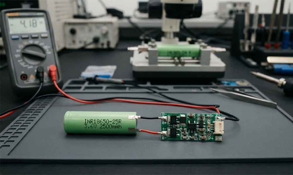
18650 lithium-ion battery may look like a simple cylindrical cell, but its safe operation depends on more than the cell itself. Voltage, current, temperature, charging conditions, and the connected equipment all affect how the battery performs.
This becomes especially important when a device uses a protected 18650 battery. A protection circuit monitors electrical conditions and can interrupt the current path when it detects certain abnormal situations. The goal is to reduce the risk of cell damage and unsafe operation.
For OEM buyers, understanding this process helps when selecting a battery for portable electronics, industrial instruments, lighting equipment, and other battery-powered products. It also helps explain why two batteries with the same nominal voltage and capacity may have different protection designs.
What Is the Basic Principle of 18650 Battery Protection?
18650 protection circuit generally combines a monitoring component, switching components, and supporting electrical parts.
The monitoring circuit checks conditions such as cell voltage and current. When the circuit detects a condition that exceeds its configured limits, it controls the switching components to interrupt or restrict the current path.
A simplified protection system includes three main parts:
- 18650 lithium-ion cell: Stores and delivers electrical energy.
- Protection IC: Monitors selected electrical conditions and determines when protection should activate.
- MOSFETs: Act as electronic switches that can disconnect the charging or discharging path.
The exact arrangement depends on the protection board design. Some circuits use separate switching paths for charging and discharging, while others use a different configuration suited to the application.
Protection is not the same as preventing every possible battery failure. It is an electrical safeguard designed around specified operating conditions. It cannot compensate for a damaged cell, unsuitable charger, poor assembly, or an application that exceeds the battery’s design limits.

How Does 18650 Protection Circuit Monitor the Battery?
Voltage Monitoring
Cell voltage provides important information about its electrical condition. During charging, voltage rises. During discharge, voltage falls.
The protection IC monitors the cell voltage against predefined thresholds. When the voltage reaches an overcharge or over-discharge protection threshold, the circuit can switch off the relevant current path.
These thresholds are set by the protection circuit design. They should match the chemistry and specifications of the cell.
For example, many conventional 3.6V or 3.7V nominal lithium-ion cells use a charging limit around 4.2V, but this value should never be assumed for every lithium-based chemistry. The cell manufacturer’s datasheet is the reference for the correct charging voltage.
Current Monitoring
A protection circuit may also detect excessive current caused by overloads or short circuits.
Depending on the design, current detection may use a sensing resistor, MOSFET characteristics, or another circuit arrangement. When the detected condition crosses a configured threshold, the protection IC can turn off one or more MOSFETs.
The current limit is a critical selection point. A board designed for a low-current consumer device may not be suitable for equipment with high startup current or demanding power output.
For OEM projects, check both the cell’s discharge capability and the protection circuit’s current rating. The battery can only deliver the performance allowed by the complete electrical system.
How Does Overcharge Protection Work?
Overcharging occurs when a lithium-ion cell is charged beyond its specified voltage limit. It can accelerate cell degradation and create serious safety risks.
In a protected 18650 battery, the protection IC monitors the cell voltage during charging. If the voltage reaches the circuit’s overcharge threshold, the IC changes the state of the switching components to interrupt the charging path.
The charging current then stops or is restricted according to the circuit design.
This process does not replace a proper charging system. The charger should still provide the correct voltage and current profile for the cell. The protection circuit is a secondary safeguard, not a reason to use an incompatible charger.
OEM engineers should verify:
- The cell’s maximum charging voltage.
- The protection circuit’s overcharge detection threshold.
- The protection delay and recovery conditions.
- Compatibility between the battery and the intended charger.
These details matter when a battery is installed inside a product whose charging electronics are designed by a separate manufacturer.

How Does Over-Discharge Protection Work?
Over-discharge happens when a cell is discharged below its specified lower-voltage limit.
When the voltage falls to the protection circuit’s configured threshold, the protection IC can switch off the discharge path. This helps prevent the cell from remaining in an excessively discharged state during normal use.
The device may suddenly stop working even though the battery still appears to contain some energy. In a protected battery, this shutdown can be the expected response of the protection circuit rather than a sign that the cell is completely empty.
Recovery behavior varies between designs. Some circuits reconnect the discharge path when a charger is attached or when the cell voltage recovers under defined conditions. Other designs use different recovery logic.
For product developers, this behavior should be considered during low-battery testing. A device should not rely on repeated protection cutoffs as its normal method of battery management.
A well-designed product can provide a low-battery warning or shut down before the battery protection circuit has to intervene.
How Does Short Circuit and Overcurrent Protection Work?
Overcurrent Protection
Overload can occur when a connected device draws more current than the battery system is designed to provide. This may happen during motor startup, a sudden increase in load, or an equipment fault.
If the current exceeds the protection circuit’s configured threshold for the required detection period, the protection IC may turn off the MOSFETs and interrupt the current path.
The circuit must be selected carefully because normal startup current and abnormal overload current are not always the same. A threshold that is too low can cause nuisance shutdowns. A threshold that is too high may fail to provide the intended level of protection.
Short Circuit Protection
A short circuit can create a rapid increase in current. The protection circuit is designed to detect certain short-circuit conditions and disconnect the current path quickly.
However, response time, current threshold, wiring resistance, and the switching components all affect real-world performance. A protection board should not be treated as a guarantee against every short circuit or wiring fault.
OEM battery assemblies also need suitable insulation, secure connections, appropriate conductors, and careful assembly procedures. Protection electronics work alongside these measures rather than replacing them.
What Role Do MOSFETs Play in Battery Protection?
MOSFETs are semiconductor switches used to control the current path between the cell and the external circuit.
During normal operation, the switches remain in a state that allows charging or discharging. When the protection IC detects a fault condition, it changes the MOSFET control signal to interrupt the affected path.
The MOSFET selection affects several practical parameters:
- Maximum supported current.
- Voltage drop during normal operation.
- Heat generated under load.
- Switching behavior and response.
- Compatibility with the protection IC.
A board may advertise a particular current rating, but the rating should be evaluated alongside operating temperature, board layout, copper thickness, connection quality, and test conditions.
For OEM buyers, it is not enough to ask whether a battery has a protection board. The more useful question is whether the complete protection design matches the device’s electrical requirements.
Does 18650 Protection Circuit Reset Automatically?
The answer depends on the protection IC, MOSFET arrangement, fault condition, and board design.
After an overcurrent or short-circuit event, some circuits recover when the load is removed. Others may require the cell voltage to recover or a charger to be connected. Overcharge and over-discharge protection also have their own recovery conditions.
This can create differences in user experience.
For example, two visually similar protected 18650 batteries may respond differently after a device shuts down under a heavy load. One may recover after the load is disconnected, while another may need a charging connection before normal operation resumes.
When evaluating a battery for an OEM product, test the recovery behavior under the actual operating conditions. Confirm whether the product’s firmware, user instructions, and charging design account for the expected behavior.
Never assume that every protection board has the same cutoff thresholds or reset sequence.
Is Single-Cell Protection the Same as a Battery Pack BMS?
No. A protection circuit installed on an individual 18650 cell is not automatically equivalent to a battery management system designed for a multi-cell pack.
A protected single cell generally focuses on the electrical conditions monitored by its own protection circuit. A multi-cell battery pack may need additional functions depending on its configuration and application.
These can include:
- Monitoring individual series-connected cell groups.
- Managing overcharge and over-discharge conditions.
- Controlling pack-level current.
- Balancing cell groups where required.
- Monitoring temperature through suitable sensors.
- Communicating with the host device or charger.
Not every BMS includes all these functions, and the required feature set depends on the pack design.
A pack assembled from several protected cells is not necessarily the best solution. Individual protection circuits can interact with a pack-level BMS or affect current delivery in ways that were not intended by the system designer.
For multi-cell applications, the cell arrangement, pack voltage, charging method, load current, and protection strategy should be designed as one system.

What Should OEM Buyers Check Before Choosing a Protected 18650 Battery?
The word “protected” alone does not provide enough information to select a battery.
Start with the device’s electrical requirements. Confirm the nominal voltage, maximum charging voltage, expected capacity, continuous discharge current, peak current, and available installation space.
Next, review the protection circuit. Important details include overcharge and over-discharge thresholds, overcurrent and short-circuit response, recovery behavior, and rated operating conditions.
Mechanical fit also matters. Some protected 18650 batteries are longer than comparable unprotected cells because the protection circuit adds components at one end. A tight battery compartment may not accommodate the additional length.
For OEM and wholesale orders, it is useful to confirm the following information with the supplier:
- Cell manufacturer, chemistry, and datasheet.
- Rated capacity and test conditions.
- Protection circuit specification and cutoff thresholds.
- Continuous and peak discharge requirements.
- Battery dimensions, terminal design, and connection method.
- Charging compatibility and required operating temperature.
- Required testing, documentation, and certification scope.
- Sample availability and production consistency.
If the battery will be integrated into a custom product, request a sample and test it in the final device. Confirm startup current, shutdown behavior, charging performance, and recovery after protection activation before approving mass production.
Final Thoughts on 18650 Battery Protection
18650 battery protection works by monitoring selected electrical conditions and controlling switching components when those conditions exceed configured limits. Overcharge, over-discharge, overcurrent, and short-circuit protection can all help reduce specific risks, but the actual functions depend on the circuit design.
For OEM buyers, the best protected battery is not simply the one with the most features. It is the battery whose cell, protection circuit, current capability, dimensions, charging requirements, and recovery behavior match the product.
For commercial projects, explore our 18650 Lithium Battery options and confirm the required specifications before selecting a standard cell or developing a customized battery solution.
FAQs
1. How does protection work in 18650 lithium battery?
A protection IC monitors conditions such as cell voltage and current. When a configured threshold is exceeded, it controls MOSFET switches to interrupt the relevant charging or discharging path.
2. Does 18650 protection circuit stop overcharging?
It is designed to disconnect or restrict the charging path when the cell reaches its configured overcharge threshold. A compatible charger is still necessary.
3. Can 18650 protection circuit prevent every short circuit?
No. It can respond to certain detected short-circuit conditions, but it cannot eliminate every risk. Proper wiring, insulation, assembly, and system-level protection remain important.
4. Why does a protected 18650 battery suddenly stop working?
The protection circuit may have activated because of low cell voltage, excessive current, a short circuit, or another monitored condition. Recovery depends on the circuit design and the cause of the cutoff.
5. Is a protected 18650 cell enough for a multi-cell battery pack?
Not necessarily. A multi-cell pack may require a dedicated BMS and additional voltage, current, temperature, or balancing functions, depending on the pack configuration and application.
-

12V 4400 mah Lithium ion 3S2P 18650 Battery Pack
-

18650 2000mAh 3.7 volt Lithium-ion Battery
-

18650 20V 3.0Ah Cordless Drill battery
-

18650 22.2V 7.8Ah 2600Mah 6S3P Rechargeable Battery Pack
-

18650 2600mAh Rechargeable Lithium-Ion Battery 3.7V
-

18650 3.7V 10Ah Li-Ion Power Battery Pack
-

18650 3.7V 3300mah Rechargeable Lithium ion Battery
-

18650 7S7P 24V 14Ah Lithium ion Electric Scooter Battery Pack
-

18650 battery 3.7V 1500mAh Lithium-Ion Battery
-

18650 Battery 3500 mah Rechargeable Battery Cells
-

18650 Electric Scooter 48V 13000mAh Lithium Battery
-

2600mAh 3S1P 11.1V 18650 Battery Packs
-

3.7V Li ion Rechargeable 3000mah 18650 Battery Cell
-

36V 5200mAh 10S2P 18650 Battery Pack
-

48v 4400mah 13S2P 18650 Rechargeable Battery Pack
-

7S2P 24V 18650 Lithium Battery Pack
-

Electric Scooter 36V 4400mAH 10S2P 18650 Battery Pack
-

ICR 18650 Battery 2200mah 3.7V
Leave a Reply