
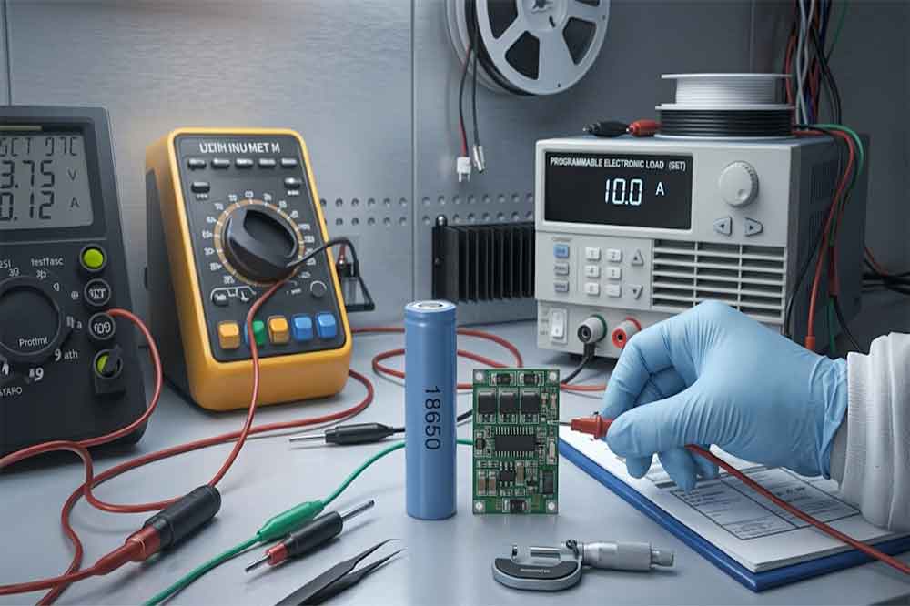
Choosing the right current rating for an 18650 protection circuit is important when developing a reliable lithium-ion battery. If the board cannot support the device’s normal load, the battery may disconnect during operation. If the board’s protection threshold is poorly matched to the cell and application, the circuit may not respond as intended when a fault occurs.
However, choosing a board with the highest advertised amp rating is not always the right solution. The cell, protection circuit, wiring, connector, and operating environment must work together.
For OEM manufacturers and bulk buyers, the first step is to understand what the current rating actually means. Then compare it with the battery cell’s discharge specification and the device’s real operating requirements.
What Does the Current Rating of a Protection Circuit Mean?
The current rating describes how much current a protection board is designed to carry under specified conditions. It is not a universal value that can be applied to every installation.
A board’s practical current capability can depend on its MOSFETs, PCB copper thickness, component layout, solder joints, connection method, ambient temperature, and cooling conditions. Two boards with similar advertised ratings may perform differently in a finished battery assembly.
Ask the supplier how the rating was determined. A useful specification should clarify the continuous current, permitted peak current and duration, operating temperature, and any conditions needed to achieve the stated performance.

Continuous Current vs Peak Current
Continuous current is the current the circuit is designed to carry for an extended period under specified conditions. Peak current is a higher current that may occur briefly, such as during motor startup or capacitor charging.
These values should not be treated as interchangeable. A board may support a short transient but not the same current continuously. Conversely, a board that supports the device’s steady operating current may disconnect if a startup surge exceeds its overcurrent threshold.
Consider a portable device that normally draws a moderate current but briefly demands much more when a motor starts. Checking only the average current could lead to a protection board that works during a bench test but disconnects in actual use.
For this reason, record both the normal operating current and the highest expected transient current before selecting the board.
Overcurrent Protection Threshold vs Operating Current
The overcurrent protection threshold is the condition at which the circuit is designed to interrupt current. It is not the same as the board’s recommended continuous operating current.
The threshold may have a tolerance, and the response can depend on the duration and shape of the current event. A brief transient and a sustained overload may not trigger the circuit in the same way.
A suitable design should allow normal operation while providing the intended response to fault conditions. Do not simply set the threshold as high as possible to prevent unwanted cutoffs. The selected value must remain compatible with the cell, circuit, wiring, and product safety requirements.
Start With the 18650 Cell’s Discharge Rating
The protection board cannot make a cell safely deliver more current than the cell is designed to provide. Always check the datasheet for the exact 18650 model being used.
Cells can have similar dimensions and nominal voltages but very different discharge capabilities. Capacity alone does not tell you the maximum permitted current. A higher-capacity cell is not automatically suitable for a higher-current application.
Check the manufacturer’s continuous discharge limit, any specified pulse-current conditions, and the temperature requirements. If the datasheet does not specify a permissible pulse current, do not assume that a short burst above the continuous limit is acceptable.
The cell’s condition also matters. Aging, low temperature, internal resistance, and the state of charge can affect voltage sag and heat generation. A battery that performs adequately when fully charged may behave differently near the lower end of its operating range.
For a pack using cells in parallel, the available current depends on the individual cells, their matching, interconnections, and the overall design. Do not divide the device’s current equally among cells unless the electrical arrangement and current sharing support that assumption.

Calculate the Current Required by the Device
Start with the device’s electrical requirements rather than the protection board catalogue. If the product documentation gives current values, use those values and confirm them through measurement where necessary.
When only power and voltage are available, a basic estimate is:
Current (A) = Power (W) ÷ Voltage (V)
For example, a device consuming 30W from a battery operating at 3.0V would require approximately 10A at that point, assuming 30W is the electrical power drawn from the battery. If the 30W figure describes output power from a converter, the battery-side current will be higher because conversion losses must also be considered.
This calculation is a starting point, not a complete protection-board specification. The battery voltage changes during discharge, and some loads draw more current at lower voltage to maintain power. Motor loads and other dynamic devices may also have short startup surges.
Estimate Current From Power and Voltage
For a single-series battery, use the lowest relevant operating voltage when estimating the highest current for a constant-power load. Also consider conversion efficiency if the device uses a DC-DC converter.
For a multi-cell series pack, use the pack voltage and power requirements to estimate pack current. The protection system must then be selected for the actual battery configuration and its individual cell-group limits.
If the device’s power consumption changes significantly with operating mode, measure several conditions rather than relying on one nominal figure. Include standby, normal operation, maximum load, startup, and any brief overload conditions expected during normal use.
Account for Startup Surges
Some devices briefly draw several times their steady-state current. Motors, pumps, solenoids, transmitters, and capacitive loads are common examples.
Ask the device engineer for the peak current and its duration. If those values are unavailable, use an appropriate instrument or current probe to capture the startup waveform.
The protection board’s response time and threshold must be evaluated against that waveform. A current spike that lasts only briefly may behave differently from a sustained overload, depending on the circuit design.
Do not solve repeated cutoffs by installing a board with a higher threshold without first checking the cause. The real issue could be excessive startup current, voltage sag, a weak cell, undersized wiring, or a faulty load.
How Wiring, Connectors, and Temperature Affect Current
A protection board is only one part of the current path. Wires, connectors, welds, solder joints, and PCB traces all contribute resistance. Resistance produces heat when current flows, so a design that works briefly may become too hot during sustained operation.
Check the wire gauge, connector rating, contact quality, and assembly method. A connector that is mechanically convenient may not be suitable for the required current. Loose or poor-quality connections can create localized heating and voltage drop.
Temperature also affects performance. A board installed inside a sealed enclosure may have less opportunity to dissipate heat than the same board tested in open air. High ambient temperature can further reduce the available thermal margin.
For OEM production, verify the complete assembly under representative operating conditions. Measure temperature rise, voltage drop, and protection behavior in the intended enclosure, not just on an open workbench.
The cell itself needs appropriate thermal and mechanical design. A protection PCB does not replace correct insulation, secure cell mounting, suitable charging equipment, or product-level safety validation.
Common Mistakes When Selecting a Protection Circuit
One frequent mistake is selecting a board based on its peak-current number while ignoring continuous current. Ask for both ratings and the conditions under which they apply.
Another is assuming the PCB’s advertised current rating is automatically safe for the cell. The cell may have a lower discharge limit, and the wiring or connector may be the actual bottleneck.
A third mistake is overlooking transient loads. A device can pass a steady-current test but disconnect during startup. Test the actual load profile before approving a design.
Finally, avoid comparing boards by a single number without reviewing the datasheet. Current capability, protection threshold, response time, temperature range, and physical fit all matter.
How OEM Buyers Should Verify a Board’s Current Rating
Before requesting samples or a quotation, prepare a concise electrical specification. Include the exact cell model, chemistry, nominal voltage, permitted discharge current, and expected battery configuration.
Provide the device’s normal current, maximum continuous current, startup peak, and peak duration. Explain whether the load uses a motor, switching converter, radio transmitter, or another component with dynamic current demand.
Ask the supplier to confirm the board’s continuous rating, peak rating and duration, overcurrent threshold, response behavior, and test conditions. Also confirm PCB dimensions, connection points, wire requirements, and operating temperature.

Then test samples in the real application. Verify normal startup, sustained operation, low-voltage behavior, thermal performance, and response to appropriate fault tests using a controlled engineering procedure.
If no standard board meets the requirements, a custom protection circuit or a complete custom battery assembly may be more appropriate. The design should be reviewed as a system, with the cell, protection circuit, charger, wiring, connector, and enclosure considered together.
For related selection guidance, read our 18650 protected battery complete guide and 18650 BMS vs PCB comparison.
If you are sourcing cells or developing a battery for an OEM product, explore our 18650 lithium battery options. Share the load profile and cell requirements when requesting a recommendation, so the protection circuit can be selected against real operating conditions rather than an arbitrary amp rating.
FAQ
How many amps should an 18650 protection circuit handle?
It should support the application’s continuous and peak current requirements while remaining compatible with the cell’s discharge limits, wiring, connectors, and thermal conditions. Check the actual board datasheet before selecting a rating.
Is a 10A protection board suitable for every 18650 battery?
No. The board’s rating must match the specific cell and application. Some cells cannot safely deliver 10A continuously, while some devices may require more current during startup than a particular board can support.
What is the difference between a board’s current rating and its overcurrent threshold?
The current rating describes the current the board is designed to carry under specified conditions. The overcurrent threshold is the level at which its protection function is intended to respond. They are related but not interchangeable.
Why does an 18650 protection board keep cutting off?
Possible causes include startup surges, excessive load current, voltage sag, an unsuitable cell, poor connections, or an incompatible protection threshold. Measure the load and inspect the complete battery system before changing the board.
-

12V 4400 mah Lithium ion 3S2P 18650 Battery Pack
-

18650 2000mAh 3.7 volt Lithium-ion Battery
-

18650 20V 3.0Ah Cordless Drill battery
-

18650 22.2V 7.8Ah 2600Mah 6S3P Rechargeable Battery Pack
-

18650 2600mAh Rechargeable Lithium-Ion Battery 3.7V
-

18650 3.7V 10Ah Li-Ion Power Battery Pack
-

18650 3.7V 3300mah Rechargeable Lithium ion Battery
-

18650 7S7P 24V 14Ah Lithium ion Electric Scooter Battery Pack
-

18650 battery 3.7V 1500mAh Lithium-Ion Battery
-

18650 Battery 3500 mah Rechargeable Battery Cells
-

18650 Electric Scooter 48V 13000mAh Lithium Battery
-

2600mAh 3S1P 11.1V 18650 Battery Packs
-

3.7V Li ion Rechargeable 3000mah 18650 Battery Cell
-

36V 5200mAh 10S2P 18650 Battery Pack
-

48v 4400mah 13S2P 18650 Rechargeable Battery Pack
-

7S2P 24V 18650 Lithium Battery Pack
-

Electric Scooter 36V 4400mAH 10S2P 18650 Battery Pack
-

ICR 18650 Battery 2200mah 3.7V
Leave a Reply