
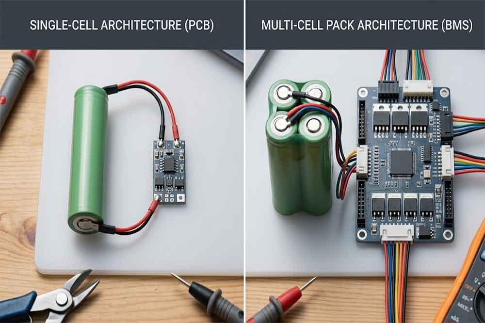
When choosing protection for an 18650 lithium-ion battery, buyers often encounter two terms: PCB and BMS. Some suppliers use them interchangeably, while others distinguish a basic protection board from a more advanced battery management system.
This can make product selection confusing, especially when an OEM project involves several cells, a compact enclosure, or a device with demanding current requirements.
The main difference is not simply the name printed on a circuit board. It is the set of functions the design provides. A basic protection PCB may disconnect the battery when it detects a defined fault. A BMS may add cell-by-cell monitoring, balancing, temperature inputs, state information, or communication features, depending on its design.
Understanding these differences helps engineers select a suitable architecture without paying for features the product does not need or overlooking important requirements.
What Is a PCB Protection Board for an 18650 Battery?
A protection circuit board, commonly called a PCB protection board, is an electronic circuit designed to help protect a lithium-ion cell or battery group against specified electrical faults.
A typical compact board may contain a protection IC, MOSFETs, resistors, and connection points. The protection circuit monitors electrical conditions and interrupts a current path when its configured thresholds are reached.
Typical Protection Functions
Depending on the specific design, a protection PCB may provide:
- Overcharge protection.
- Over-discharge protection.
- Overcurrent protection.
- Short-circuit protection.
Not every board offers the same functions or thresholds. Current ratings, response times, recovery behavior, and temperature limits also vary. Buyers should check the actual datasheet rather than assume that every board provides identical protection.
A compact protection PCB is often suitable for a single-series lithium-ion group when its voltage thresholds and current capability match the selected cells and the application.
However, a protection board does not replace a compatible charger, correct cell selection, suitable wiring, or product-level safety testing.
What Is a BMS in an 18650 Battery Pack?
A battery management system, or BMS, monitors and manages a battery according to the requirements of the system. Its functions can range from relatively simple protection to more advanced monitoring and control.
The exact capabilities depend on the product. The term BMS alone does not guarantee that a board includes balancing, temperature monitoring, data communication, or state-of-charge estimation.

Monitoring Multiple Series Cells
A battery pack made from multiple cells in series has a higher total voltage than a single cell. More importantly, each series group can behave differently as the pack charges and discharges.
If the system monitors only the pack’s total voltage, a weaker or more highly charged group may not be identified early enough. A suitable multi-series BMS can monitor individual series-group voltages and respond to conditions defined by its design.
For example, a 3S battery pack contains three series-connected cell groups. Its total voltage does not show the exact voltage of each group. Individual monitoring can therefore be important when designing the pack’s protection strategy.
Cells connected in parallel form a group at the same nominal voltage. A 1S2P arrangement has two cells in parallel but still has one series group. The required protection architecture depends on the complete battery design, not just the number of physical cells.
Cell Balancing and Other BMS Features
Some BMS products include cell balancing. Balancing helps manage voltage differences between series groups during charging or under specified operating conditions. This can be useful in multi-series packs, but it is not included in every BMS.
Depending on the project, a BMS may also support temperature sensors, current measurement, state-of-charge estimates, fault reporting, or communication with the host device.
These features matter when the battery must exchange information with a controller, charger, display, or industrial equipment. For a simple product, however, an advanced BMS may add cost, wiring, space, and development work without providing a meaningful benefit.
18650 BMS vs PCB: Key Differences
The practical difference is the scope of monitoring and control. A basic protection PCB generally focuses on defined protective cutoffs. A more capable BMS may coordinate protection with cell monitoring, balancing, temperature inputs, and system communication.
| Feature | Basic protection PCB | More capable BMS |
|---|---|---|
| Overcharge protection | Common, depending on design | Common, depending on design |
| Over-discharge protection | Common, depending on design | Common, depending on design |
| Overcurrent and short-circuit protection | Often available | Often available |
| Individual series-group monitoring | Depends on architecture; basic 1S boards monitor one group | Common in multi-series designs |
| Cell balancing | Usually not included in a basic board | Available on selected models |
| Temperature monitoring | Model-dependent | Available on selected models |
| Communication | Usually limited or absent | Available on selected models |
| Typical integration | Compact and relatively simple | May require more wiring and configuration |
This table describes common product categories, not universal rules. Some single-cell protection boards are sophisticated, and some products marketed as BMS units have only basic functions. Always verify the model’s actual specification.
Protection, Monitoring, and Balancing
Protection and management are related, but they are not the same task.
Protection responds to conditions such as excessive voltage or current. Monitoring provides information about the battery’s operating state. Balancing addresses differences between series groups when the selected BMS supports that function.
A project may need all three, or only some of them. The engineering requirement should determine the design rather than the product label.
For a detailed explanation of the related terms, see our guide to 18650 battery protection circuit, PCB, PCM and BMS.
Cost, Complexity, and Integration
A basic protection PCB can be smaller and easier to integrate into a compact single-cell product. A BMS with more sensing and communication functions may require additional components, connections, configuration, and validation.
But choosing the cheapest board is not always the lowest-cost solution. If the product needs individual cell monitoring or communication, a basic board may fail to meet the requirements and require redesign later.
Compare the complete solution: board cost, assembly time, wiring, firmware integration, enclosure space, testing, and expected production volume.
Does a 1S 18650 Battery Need a BMS or PCB?
A single-series 18650 design often uses a compact protection PCB. For example, a portable electronic device using one cell may need overcharge, over-discharge, overcurrent, and short-circuit protection without requiring a multi-series monitoring system.
A 1S1P battery contains one cell. A 1S2P battery contains two cells connected in parallel. Both have one series group, but the parallel arrangement changes capacity and may change the current requirements. The cells must be compatible and appropriately assembled.
Do not assume that every 1S application can use the same board. Check the cell chemistry, voltage thresholds, continuous current, peak current, charging arrangement, dimensions, and connector.
A more advanced BMS may still be appropriate for a single-series application if the product needs temperature monitoring, communication, fuel-gauge information, or other functions. The correct choice depends on the feature requirements, not the 1S label alone.
When Does a Multi-Cell Battery Pack Need a BMS?
Multi-series packs generally need a protection and monitoring architecture designed for the number of series groups and the risks of the application. A suitable BMS can monitor individual group voltages and may provide balancing, temperature monitoring, and other management functions.
For example, a 3S or 4S pack may require individual series-group monitoring because the cells do not always remain at identical voltages throughout service. The system design should account for cell matching, charging behavior, operating current, thermal conditions, and fault response.
The BMS must also match the pack’s chemistry and voltage limits. A board designed for one series count or chemistry should not be assumed suitable for another.
In higher-demand applications, the design may require additional features such as communication with the main controller, fault logging, or temperature-based charge and discharge restrictions. Define these needs before selecting a standard board.

How to Choose the Right Protection Architecture
Start by writing down what the battery must do. This is more useful than starting with a supplier’s product list.
Current, Voltage, and Cell Chemistry
Confirm the cell model, chemistry, nominal voltage, maximum charging voltage, and permitted discharge current. Then calculate or measure the device’s normal current, maximum sustained current, and startup surge.
The protection circuit’s current capability must be compatible with the cell, wiring, connector, and thermal conditions. A higher board current rating cannot make an unsuitable cell safe for the load.
Balancing, Temperature, and Communication
Ask whether the application needs individual series-group monitoring, balancing, temperature sensors, or communication. If the device must read battery status or control charging, specify the required interface and data.
Mechanical integration matters as well. Check PCB dimensions, wire routing, connector type, insulation, mounting, and enclosure clearance.
For the next step, evaluate samples in the intended product. Test normal charging and discharging, cutoff behavior, transient loads, temperature rise, and any required communication or balancing functions under a documented engineering plan.
Common OEM Selection Mistakes
One common mistake is assuming that every BMS includes balancing or communication. These are model-specific features and must be confirmed.
Another is selecting a PCB by current rating alone. The cell itself, the connector, the wiring, and the operating temperature can limit the complete system.
Some buyers also overlook series count. A 1S protection board is not a substitute for a properly designed multi-series BMS. Finally, a protection board should not be treated as the entire battery safety system: charger compatibility, mechanical design, cell quality, assembly controls, and validation remain important.
For OEM projects, send the supplier the battery configuration, cell datasheet, load profile, charging method, required protection functions, available space, connector details, and production quantity. This gives the supplier a clearer basis for recommending a standard PCB, a BMS, or a custom protected battery assembly.
Explore our 18650 lithium battery options when planning a battery sourcing project. The best solution is the one that meets the verified application requirements with an appropriate level of protection and management—not necessarily the board with the most features.
FAQ
What is the difference between an 18650 BMS and a PCB?
A basic protection PCB usually focuses on protective cutoff functions. A BMS may also provide individual cell-group monitoring, balancing, temperature monitoring, or communication. Actual functions depend on the specific model.
Does a single 18650 battery need a BMS?
A single-series 18650 application often uses a suitable protection PCB. A more advanced BMS may be needed if the product requires additional monitoring, temperature sensing, or communication features.
Does every 18650 BMS support cell balancing?
No. Balancing is a model-specific feature. Check the BMS datasheet to confirm whether balancing is supported, which cell configuration it covers, and how it operates.
Can I use a 1S protection PCB in a 3S 18650 battery pack?
A basic 1S board should not be treated as a complete BMS for a 3S pack. A multi-series pack needs a protection architecture designed for its series configuration and applicable monitoring requirements.
-

12V 4400 mah Lithium ion 3S2P 18650 Battery Pack
-

18650 2000mAh 3.7 volt Lithium-ion Battery
-

18650 20V 3.0Ah Cordless Drill battery
-

18650 22.2V 7.8Ah 2600Mah 6S3P Rechargeable Battery Pack
-

18650 2600mAh Rechargeable Lithium-Ion Battery 3.7V
-

18650 3.7V 10Ah Li-Ion Power Battery Pack
-

18650 3.7V 3300mah Rechargeable Lithium ion Battery
-

18650 7S7P 24V 14Ah Lithium ion Electric Scooter Battery Pack
-

18650 battery 3.7V 1500mAh Lithium-Ion Battery
-

18650 Battery 3500 mah Rechargeable Battery Cells
-

18650 Electric Scooter 48V 13000mAh Lithium Battery
-

2600mAh 3S1P 11.1V 18650 Battery Packs
-

3.7V Li ion Rechargeable 3000mah 18650 Battery Cell
-

36V 5200mAh 10S2P 18650 Battery Pack
-

48v 4400mah 13S2P 18650 Rechargeable Battery Pack
-

7S2P 24V 18650 Lithium Battery Pack
-

Electric Scooter 36V 4400mAH 10S2P 18650 Battery Pack
-

ICR 18650 Battery 2200mah 3.7V
Leave a Reply