
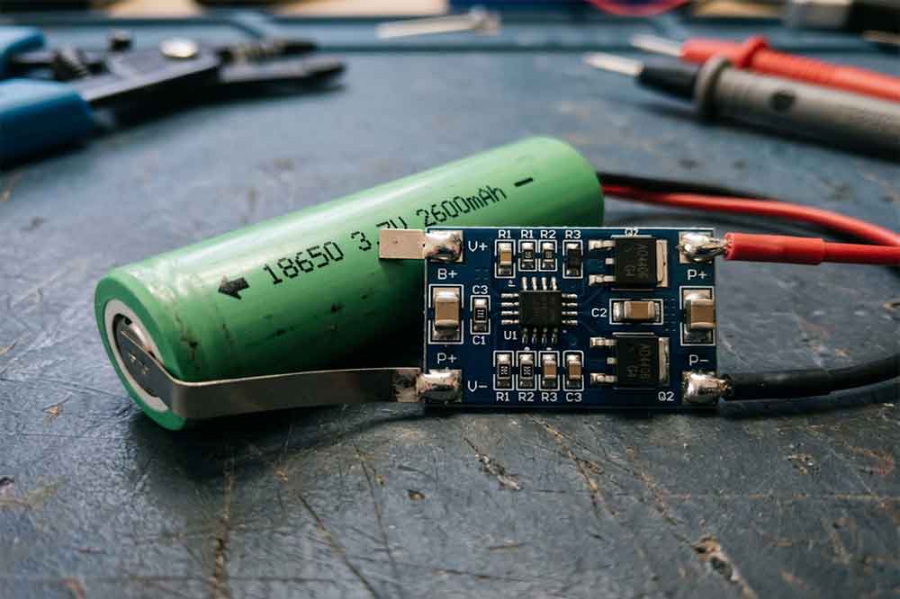
18650 lithium-ion battery protection circuit is a small component, but its role can be important in the performance and safety of a battery-powered product. It helps monitor certain electrical conditions and can disconnect the cell when predefined limits are reached.
For OEM manufacturers and battery buyers, knowing that a cell has a protection PCB is not enough. The circuit must be suitable for the cell chemistry, voltage range, current demand, charging system, and intended application.
Some buyers focus mainly on battery capacity or price. During product testing, however, an unsuitable protection circuit may cause unexpected shutdowns, compatibility problems, or inadequate fault response. Understanding what the circuit can and cannot protect against makes battery selection more practical.
What Is 18650 Protection Circuit?
18650 protection circuit is an electronic circuit designed to monitor selected battery conditions and interrupt charging or discharging when specified fault thresholds are reached.
The circuit commonly includes a protection IC and switching components such as MOSFETs. Depending on the design, it may respond to excessive cell voltage, low cell voltage, excessive current, or a short circuit.
The exact functions are not identical across all protection boards. Some are designed for relatively simple single-cell applications, while others have different current ratings, cutoff thresholds, or recovery behavior.
The Role of the PCB in a Protected Cell
In a protected 18650 battery, the protection circuit is usually integrated into the cell assembly. This can make the overall battery longer than a comparable unprotected cell.
The PCB does not increase the cell’s inherent capacity or automatically improve its discharge performance. Instead, it provides defined protection functions around the cell’s operating limits.
For example, a battery-powered device may continue to operate normally until the cell voltage falls below the protection circuit’s cutoff threshold. The circuit can then interrupt the discharge path. The device may stop working even though the battery has not reached the same voltage at which it would normally be considered fully discharged under another system’s specifications.
This is one reason why the protection circuit and the equipment should be evaluated together.
For a broader explanation of the components involved, see our guide to the 18650 battery protection circuit, PCB, PCM and BMS.
Four Main Conditions 18650 Protection Circuit Can Address
The following functions are common in lithium-ion protection designs, but buyers should verify which ones are included in the specific board being supplied.

Overcharge Protection
Overcharge protection helps prevent a cell from continuing to charge beyond the voltage limit defined by the protection design.
When the circuit detects that the cell voltage has reached its overvoltage threshold, it can disconnect the charging path. The exact threshold, detection delay, and recovery conditions depend on the circuit specification.
This function is not a replacement for a correctly designed charger. The charging system must still use the appropriate voltage and current for the cell chemistry and manufacturer’s requirements.
For OEM projects, engineers should confirm that the charger’s operating limits and the protection circuit’s thresholds are compatible. Relying on the protection board to correct a poorly configured charging system is not an appropriate design strategy.
Over-Discharge Protection
Over-discharge protection helps prevent the cell voltage from falling below the lower limit defined by the circuit.
This can matter in devices that remain connected to a load for long periods. Even when the product appears to be switched off, standby electronics may continue drawing a small current.
If the voltage reaches the circuit’s undervoltage threshold, the board may interrupt the discharge path. The product may shut down or become temporarily unresponsive until the battery is charged or the protection circuit recovers.
Buyers should check the cutoff threshold and recovery behavior when selecting a protected cell for equipment with low-voltage operating requirements.
Overcurrent Protection
Overcurrent protection responds when current exceeds a specified level or satisfies the circuit’s fault-detection conditions.
This matters when a device has a high startup current, sudden load changes, or a motor that briefly draws more current during acceleration. A protection circuit that is unsuitable for the load may disconnect the battery even when the cell itself could otherwise support the required current.
The circuit’s current rating must therefore be checked alongside the cell’s discharge rating. Wiring, connectors, and other components must also support the intended current.
There is no single current rating suitable for every 18650 protection PCB. Buyers should provide both continuous current and peak-current requirements when requesting a quotation or sample.
Short-Circuit Protection
A short circuit can create a rapid increase in current and generate heat. A suitable protection circuit may detect this condition and interrupt the current path.
The response depends on the board’s design, detection threshold, response time, and switching components. Different products may also behave differently after the fault is removed.
Short-circuit protection should not be treated as permission to deliberately short a battery during informal testing. Battery validation should follow controlled procedures using appropriate equipment and qualified personnel.
Mechanical design remains important, too. Insulation, cell holders, wiring, connectors, and assembly quality all help reduce the possibility of accidental short circuits.
What 18650 Protection Circuit Cannot Guarantee
A protection PCB addresses specified electrical fault conditions. It does not eliminate every battery hazard.
It cannot guarantee that a damaged cell will remain safe, that an incompatible charger will operate correctly, or that an incorrectly assembled battery pack will perform as intended. The circuit may also lack temperature monitoring or other functions required by the application.
For example, a battery used in industrial equipment may be exposed to vibration, repeated load changes, or a wider operating-temperature range than a consumer device. These conditions may require additional engineering measures beyond the functions provided by a basic single-cell PCB.
The quality of the cell itself is equally important. A protection circuit cannot turn an unsuitable or defective cell into a reliable battery.
This is why a protected battery should be viewed as one part of the complete product design. Cell quality, charging control, thermal management, mechanical protection, and appropriate validation remain necessary.
How Protection Circuit Ratings Affect Battery Selection
Two protected 18650 batteries may look similar but behave differently because their circuits have different specifications.
Voltage Thresholds
Check the cell chemistry and the specified charging and discharging limits before choosing a protection board. The overcharge and over-discharge thresholds must be suitable for the cell and application.
Do not assume that every lithium-ion cell uses identical voltage limits. Chemistry, cell design, and manufacturer specifications matter.
Continuous and Peak Current
Continuous current describes the load the battery must support during normal operation. Peak current describes a higher demand that occurs for a limited period.
For equipment with motors, wireless transmitters, or other changing loads, the peak demand may be particularly important. Ask the supplier to confirm the circuit’s operating-current rating and fault-response behavior, rather than relying on the cell capacity rating alone.
Physical Size and Connection Design
The protection circuit can affect the battery’s total dimensions and terminal arrangement. This may determine whether a protected cell fits an existing battery holder.
Also check the terminal design, connector requirements, contact pressure, and installation method. For OEM projects, these details should be confirmed with a physical sample before the product enclosure is finalized.
Is Single-Cell Protection PCB Enough for Battery Pack?
Not necessarily. A single-cell protection circuit and a battery management system for a multi-cell pack are designed for different system requirements.
A multi-cell battery pack may need monitoring across several cell groups, coordinated charging and discharging control, temperature monitoring, and cell balancing. The required functions depend on the series-parallel configuration and intended use.
Adding protected cells to a multi-cell pack does not automatically replace a properly designed pack-level protection system. Individual cell boards may not provide coordinated monitoring or balancing across series-connected groups.
For a custom battery pack, the engineering team should define the protection architecture before choosing the cell configuration. Our article on how 18650 battery protection works provides more background on the underlying process.

What OEM Buyers Should Confirm With Battery Supplier
Before ordering protected 18650 batteries in bulk, provide the supplier with the application’s actual requirements.
Start with the cell chemistry, nominal voltage, capacity, and charging limits. Then specify the continuous and peak current, physical dimensions, connector, operating temperature, and available installation space.
Ask the supplier to identify the protection functions included in the proposed circuit. Request the relevant current ratings, cutoff thresholds, and recovery behavior where applicable. If the product requires temperature monitoring or other specialized functions, confirm these explicitly.
For multi-cell applications, explain the series-parallel arrangement and ask how the proposed BMS or protection architecture will manage the complete pack.
Sample testing is valuable because a circuit may behave differently under the real load profile than it does during a basic bench check. Verify normal startup, sustained operation, charging behavior, and relevant fault responses using an appropriate test plan.
For production orders, also confirm cell traceability, inspection procedures, documentation, and any applicable testing or transport requirements.
Choosing 18650 Battery for Your Application
The right protection circuit is the one that matches the battery and the equipment. A small board with an unsuitable current rating may cause unnecessary shutdowns, while a circuit lacking a required protection function may not meet the application’s needs.
Single-cell products may benefit from a suitable protected 18650 battery. Multi-cell packs often require a dedicated protection and monitoring design that considers the behavior of the complete assembly.
Before selecting a product, compare the electrical specifications, physical dimensions, protection functions, and charging requirements. You can explore our 18650 lithium battery options as a starting point for discussing your application with a battery supplier.
Conclusion
18650 protection circuit can help address overcharge, over-discharge, overcurrent, and short-circuit conditions, depending on its design. However, these functions have defined limits and do not replace correct charging, suitable cell selection, or complete battery-system engineering.
For OEM and wholesale buyers, the most useful approach is to specify the application first and then confirm that the cell and protection circuit meet its requirements. Checking current capability, voltage thresholds, dimensions, and recovery behavior before mass production can help prevent avoidable integration problems.
FAQs
1. What does an 18650 protection circuit protect against?
Depending on its design, it may protect against overcharge, over-discharge, overcurrent, and short circuits. Confirm the supported functions in the actual circuit specification.
2. Does every 18650 protection PCB provide the same protection?
No. Protection thresholds, current ratings, response times, recovery behavior, and supported functions can differ between boards.
3. Can a protection circuit prevent every lithium-ion battery failure?
No. It addresses specified electrical conditions but cannot eliminate risks from physical damage, unsuitable charging, overheating, manufacturing defects, or incorrect assembly.
4. Can a protected 18650 cell be used in a multi-cell battery pack?
It depends on the pack design. Individual protected cells do not automatically provide coordinated pack-level monitoring or cell balancing. The complete protection architecture should be reviewed by a qualified battery engineer.
5. What should OEM buyers check before choosing a protection PCB?
Check cell chemistry, voltage thresholds, continuous and peak current, dimensions, connections, charging compatibility, required protection functions, and the operating environment.
For a broader overview of protected cells, battery specifications, and OEM requirements, read our 18650 protected battery complete guide.
-

12V 4400 mah Lithium ion 3S2P 18650 Battery Pack
-

18650 2000mAh 3.7 volt Lithium-ion Battery
-

18650 20V 3.0Ah Cordless Drill battery
-

18650 22.2V 7.8Ah 2600Mah 6S3P Rechargeable Battery Pack
-

18650 2600mAh Rechargeable Lithium-Ion Battery 3.7V
-

18650 3.7V 10Ah Li-Ion Power Battery Pack
-

18650 3.7V 3300mah Rechargeable Lithium ion Battery
-

18650 7S7P 24V 14Ah Lithium ion Electric Scooter Battery Pack
-

18650 battery 3.7V 1500mAh Lithium-Ion Battery
-

18650 Battery 3500 mah Rechargeable Battery Cells
-

18650 Electric Scooter 48V 13000mAh Lithium Battery
-

2600mAh 3S1P 11.1V 18650 Battery Packs
-

3.7V Li ion Rechargeable 3000mah 18650 Battery Cell
-

36V 5200mAh 10S2P 18650 Battery Pack
-

48v 4400mah 13S2P 18650 Rechargeable Battery Pack
-

7S2P 24V 18650 Lithium Battery Pack
-

Electric Scooter 36V 4400mAH 10S2P 18650 Battery Pack
-

ICR 18650 Battery 2200mah 3.7V
Leave a Reply