
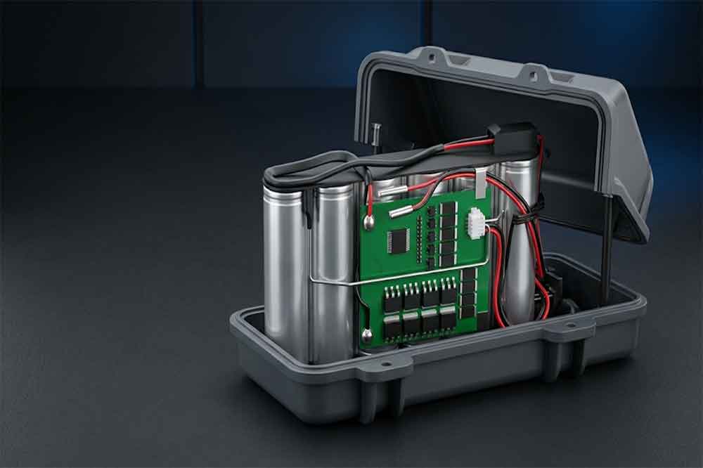
When equipment manufacturer specifies an 18650 battery pack, protection should be treated as part of the electrical and mechanical design, not as an accessory added after the cells have been selected. The protection circuit must respond to abnormal operating conditions without interfering with the equipment’s normal power demand.
For OEM battery projects, the challenge is to balance safety, output current, runtime, available space, operating temperature and service life. A battery pack designed for a portable inspection instrument may have very different requirements from one powering an industrial controller, a backup power module or a professional handheld device.
A well-designed protected 18650 battery pack starts with the application requirements. Cell selection, circuit protection, wiring, thermal management and validation must then be developed as one system.
For OEM projects requiring specific voltage, capacity, dimensions or protection functions, explore our 18650 lithium battery products to evaluate suitable battery options for your equipment.
Why Protection Must Be Designed Into 18650 Battery Pack
An 18650 lithium-ion cell stores considerable energy in a compact cylindrical format. Its performance depends on operating within the manufacturer’s specified voltage, current and temperature limits. Conditions outside those limits can accelerate degradation or create serious safety hazards.
Protection requirements depend on the equipment’s operating environment, load profile and expected service life. Our guide to protected 18650 battery pack applications explains how these requirements influence battery selection for different devices and industrial systems.
Protection circuitry helps manage foreseeable electrical faults. It does not make an unsuitable cell safe, compensate for poor assembly, or replace appropriate mechanical design and manufacturing controls.
For example, an industrial device may draw a relatively low average current but experience a substantial startup surge. If the protection circuit responds too quickly to that surge, the equipment may shut down even though the cells could otherwise support the load. Conversely, setting the current threshold too high can leave the pack inadequately protected.
Engineers therefore need to evaluate the actual load profile, including continuous current, peak current, surge duration, charging conditions and expected ambient temperature.
Protection also affects product availability. An unexpected cutoff in a monitoring device or industrial instrument can interrupt an operation. The objective is to prevent unsafe conditions while allowing the battery to support the intended duty cycle.
The Main Protection Components in a Protected 18650 Battery Pack
Protection Circuit Module (PCM)
A Protection Circuit Module, or PCM, typically monitors cell or pack voltage and controls electronic switches when specified fault thresholds are reached. Depending on the design, it can provide overcharge, overdischarge, overcurrent and short-circuit protection.
The exact functions vary between circuit designs. Some modules provide basic voltage and current protection, while others include temperature inputs or cell-balancing functions.
For a compact OEM pack, a PCM may be suitable when the application has straightforward operating requirements and does not need advanced monitoring or communication. However, the designer must confirm that the module supports the intended series configuration, charge and discharge currents, and fault-response behavior.
Battery Management System (BMS)
A Battery Management System generally provides a broader set of monitoring and control functions. Depending on its design, it may measure individual cell-group voltages, pack current and temperature, estimate state of charge, balance cells, and communicate with the host equipment.
A BMS is especially relevant when the battery is part of a larger system that needs status information or controlled shutdown behavior. Industrial instruments, connected equipment and battery-powered machinery may require communication through a defined interface, such as SMBus, CAN or UART.
The interface alone does not guarantee compatibility. The equipment and battery supplier must agree on the protocol, message definitions, addressing, fault reporting and startup sequence.
For projects that require detailed monitoring, see our related guide to protected 18650 battery pack applications and selection. The appropriate circuit depends on the complete application, not simply the nominal battery voltage.
Fuse, Temperature Sensor and Secondary Protection
Electronic protection switches are not the only protective elements available. A properly selected fuse can provide an additional interruption mechanism under specified fault conditions. Temperature sensors can help the control circuit prevent charging or discharging outside approved temperature limits.
Some designs also use thermal fuses or other independent protective devices, depending on the risk assessment and applicable product requirements.
These components need coordinated ratings. A fuse that is poorly matched to the normal operating current may open during routine startup, while an incorrectly selected fuse may fail to provide the intended protection during a fault.
A temperature sensor is only useful if its location reflects the relevant thermal condition. A sensor mounted far from a cell group experiencing localized heating may respond too slowly to provide effective protection.

How Engineers Select the Right Protection Parameters
Protection thresholds should be derived from the selected cells, electrical architecture, charger and equipment load. Copying values from another battery pack can lead to nuisance shutdowns or insufficient protection.
Selecting the right cells is only the first step in battery pack development. Before finalizing the design, engineers should understand when protected 18650 cells should be used in a battery pack and whether cell-level protection is appropriate for the intended application.
Overcharge and Overdischarge Thresholds
The maximum charging voltage must follow the cell manufacturer’s specification. The protection circuit should interrupt charging when the applicable threshold is exceeded, taking account of measurement tolerance, switching delay and the charging system’s behavior.
The minimum discharge voltage also matters. Excessive discharge can damage cells or shorten their service life. The cutoff must be coordinated with the equipment’s minimum input voltage so that the device does not become unstable before the battery protection activates.
For a series-connected pack, individual cell-group voltages are important. A pack’s total voltage may appear acceptable while one group is approaching its lower or upper limit. Where required, the BMS should monitor the individual groups rather than relying only on total pack voltage.
Overcurrent and Short-Circuit Protection
Current protection starts with the load profile. Engineers should distinguish between continuous operating current, short-duration peaks, startup inrush and abnormal fault current.
Consider an industrial instrument that normally draws 3 A but briefly requires 7 A during startup. A protection circuit selected only around the average current could interrupt normal operation. A suitable design must consider peak magnitude, duration, conductor capacity, cell discharge ratings and the circuit’s response time.
The pack’s rated current is limited by the weakest relevant component, which may include the cells, protection MOSFETs, fuse, wiring, welds, connector or thermal path. Selecting a BMS with a high advertised current rating does not automatically make the complete battery pack suitable for that current.
Short-circuit protection requires particular care because fault current can rise rapidly. Thresholds and response times must be evaluated alongside the energy available from the cell groups and the interrupting capability of the selected components.
Cell Balancing and Temperature Monitoring
Cells connected in series do not remain perfectly identical throughout their service life. Differences in capacity, internal resistance, self-discharge and temperature can cause their voltages to diverge.
Passive balancing dissipates excess energy from higher-voltage groups, while active balancing transfers energy between groups. The appropriate method depends on the pack size, operating profile, cost target and balancing requirements.
Temperature monitoring should cover the conditions that matter for the application, including charging, sustained high loads and the possibility of uneven heating. Charging limits are particularly important because the permitted temperature range may differ between charging and discharging.
How Series and Parallel Configurations Affect Protection Design
The series-parallel configuration determines pack voltage, available capacity and the protection architecture.
In a series arrangement, cell voltages add together while ampere-hour capacity remains approximately equal to that of one parallel group. Each series group must stay within its allowable voltage range. The protection system therefore needs to address imbalance and individual group limits.
In a parallel arrangement, capacity and potential current capability increase, but current sharing depends on cell characteristics, interconnections and operating conditions. Parallel cells should be appropriately matched, and the assembly process must control their initial voltage and connection quality.
For example, a 3S2P pack built from nominal 3.6 V, 3,000 mAh cells has a nominal voltage of 10.8 V and a theoretical nominal capacity of 6,000 mAh. Actual usable energy depends on cell specifications, discharge conditions, conversion losses and cutoff settings.
The BMS or PCM must support the exact configuration. A protection board designed for a 3S pack should not be assumed suitable for a 4S design, even if the physical board looks similar.
Engineers should also check charger compatibility, connector polarity, pack identification and any host-system requirements before approving the design.
Thermal Management, Wiring and Mechanical Integration
Electrical protection cannot compensate for poor thermal design. Cells, MOSFETs, connectors and conductors all generate heat, and the heat must be managed within the enclosure available to the battery.
A compact enclosure may restrict airflow and create local hot spots. The engineering review should consider cell spacing, insulating materials, conductor cross-section, weld resistance, circuit-board placement and the heat generated under sustained load.
Mechanical protection is equally important. The design should prevent cell movement, protect terminals from accidental contact, provide appropriate insulation and account for vibration or shock where the equipment will be used in demanding environments.
Connectors must support the required current and withstand the expected mating cycles. Wire routing should avoid sharp edges and pinch points, while assembly features should reduce the chance of reversed connections or damaged insulation.
For OEM projects, these details should be resolved before tooling and mass production. A circuit that works on an open test bench may perform differently once installed in a sealed housing.
Protection Testing Before Mass Production
A battery pack should pass a documented verification process before release. Testing must be planned around the product’s risk assessment, applicable standards, cell specifications and intended operating environment.
Typical engineering checks include:
- Electrical verification: Confirm pack voltage, polarity, charge behavior, discharge performance and current capability.
- Protection-function verification: Validate overvoltage, undervoltage, overcurrent and short-circuit responses using controlled, appropriate test methods.
- Temperature evaluation: Measure component and cell temperatures under representative operating loads and charging conditions.
- Mechanical inspection: Check insulation, weld quality, wire routing, connector retention and enclosure fit.
- System integration: Confirm charger compatibility, communication behavior and fault handling in the host device.
- Production consistency: Establish inspection criteria and traceability for cells, circuit boards and completed packs.
Protection testing should not be confused with transport or product certification. UN 38.3 addresses the transport testing requirements applicable to lithium batteries, while other certifications and regulatory obligations depend on the finished product and target market.
Dangerous fault tests should be conducted by qualified personnel with appropriate equipment and safety controls, not by deliberately shorting or overcharging a prototype in an uncontrolled setting.

What OEM Buyers Should Specify When Requesting a Quote
A request for a protected 18650 battery pack should provide more than nominal voltage and capacity. Missing application details can lead to repeated design revisions, incorrect component selection and delays during sample approval.
Purchasing teams and system integrators should prepare the following information:
- Required nominal voltage, maximum charging voltage and capacity.
- Continuous current, peak current and peak duration.
- Charging method and charger specifications.
- Available dimensions, enclosure drawings and connector requirements.
- Operating and charging temperature ranges.
- Required protection functions and communication protocol.
- Expected service life, duty cycle and production quantity.
- Target-market compliance and documentation requirements.
Where the equipment uses a custom connector or proprietary communication protocol, provide drawings, interface specifications or a reference unit when possible. The battery supplier can then assess whether an existing protection design is suitable or a custom BMS is required.
For volume programs, it is also worth agreeing on sample quantities, validation criteria, change-control procedures and production traceability before approving the final design.
Conclusion
A reliable protected 18650 battery pack is the result of coordinated electrical, thermal, mechanical and system-level engineering. The protection circuit must match the selected cells and the real load profile, while the enclosure, wiring, charger and host equipment must work within the same design limits.
For device manufacturers and industrial buyers, the most effective approach is to define the operating requirements early and validate the complete battery assembly before mass production. This reduces avoidable redesigns and provides a clearer basis for evaluating supplier capability.
A battery pack manufacturer should be able to explain its protection architecture, provide relevant test documentation and confirm which parameters can be customized for the project.
Frequently Asked Questions
1. What protection functions should a protected 18650 battery pack include?
Common functions include overcharge, overdischarge, overcurrent and short-circuit protection. Depending on the application, the design may also require temperature monitoring, cell balancing, communication and additional independent protective devices.
2. Is a PCM sufficient for an industrial 18650 battery pack?
A PCM may be sufficient for applications with straightforward protection requirements. Equipment requiring cell-level monitoring, balancing, fault reporting or communication with a controller may need a more advanced BMS.
3. How does the series configuration affect battery pack protection?
The number of series-connected cell groups determines the pack’s voltage range and affects protection-board selection. Individual group monitoring may be necessary to prevent one group from exceeding its permitted voltage limits.
4. Can the protection circuit be customized for an OEM battery pack?
Yes. Protection thresholds, current ratings, temperature sensing, connectors and communication functions may be customized, subject to component capabilities and engineering validation.
5. What information is needed to develop a protected 18650 battery pack?
Provide the required voltage and capacity, continuous and peak current, dimensions, charging method, operating temperatures, protection functions and target production volume. Communication and certification requirements should also be identified early.
Related Products
-

12V 4400 mah Lithium ion 3S2P 18650 Battery Pack
-

18650 2000mAh 3.7 volt Lithium-ion Battery
-

18650 20V 3.0Ah Cordless Drill battery
-

18650 22.2V 7.8Ah 2600Mah 6S3P Rechargeable Battery Pack
-

18650 2600mAh Rechargeable Lithium-Ion Battery 3.7V
-

18650 3.7V 10Ah Li-Ion Power Battery Pack
-

18650 3.7V 3300mah Rechargeable Lithium ion Battery
-

18650 7S7P 24V 14Ah Lithium ion Electric Scooter Battery Pack
-

18650 battery 3.7V 1500mAh Lithium-Ion Battery
-

18650 Battery 3500 mah Rechargeable Battery Cells
-

18650 Electric Scooter 48V 13000mAh Lithium Battery
-

2600mAh 3S1P 11.1V 18650 Battery Packs
-

3.7V Li ion Rechargeable 3000mah 18650 Battery Cell
-

36V 5200mAh 10S2P 18650 Battery Pack
-

48v 4400mah 13S2P 18650 Rechargeable Battery Pack
-

7S2P 24V 18650 Lithium Battery Pack
-

Electric Scooter 36V 4400mAH 10S2P 18650 Battery Pack
-

ICR 18650 Battery 2200mah 3.7V
Leave a Reply