
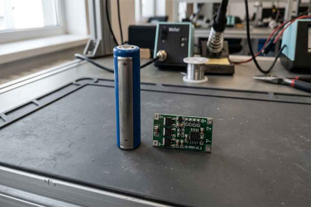
Choosing a 1S 18650 protection board is not simply a matter of finding a small PCB that fits beside a battery cell. The board must match the cell chemistry, operating current, charging method, available space, and electrical requirements of the finished product.
For OEM manufacturers and battery buyers, a mismatch can lead to nuisance cutoffs, poor device performance, difficult assembly, or inadequate protection. A board that works in a low-power handheld device may not be suitable for equipment with a motor, a radio transmitter, or a high startup current.
This guide explains what to check before selecting a 1S 18650 protection board and what information to provide when requesting a quotation or a custom battery solution.
What Is a 1S 18650 Protection Board?
A 1S 18650 protection board is a compact electronic circuit designed to monitor and protect a single-series-group lithium-ion battery. In a common 1S configuration, one 18650 cell is connected to the board. A 1S1P arrangement uses one cell, while a 1S2P arrangement uses two cells connected in parallel.
The number of cells in parallel can change the available capacity and current capability, but it does not change the basic series voltage of the group. The cells and protection circuit must still be designed to operate together.
What 1S Means in a Lithium-Ion Battery
The letter S means cells connected in series. A 1S battery has one series group, while a 2S battery has two series-connected groups.
A conventional rechargeable lithium-ion 18650 cell is often described as 3.6V or 3.7V nominal. These figures are nominal voltage labels, not the full charging voltage. The actual charging limit depends on the specific cell chemistry and manufacturer specifications.
A protection board for a single-series lithium-ion group is therefore different from a board designed for a multi-series battery pack. Do not select a board based only on the physical appearance of the PCB.
The Main Components of a Protection Board
A typical protection circuit may include a protection IC, MOSFETs, resistors, and other small electronic components. The circuit monitors battery conditions and controls the current path when a defined fault threshold is reached.
Depending on its design, the board may provide overcharge, over-discharge, overcurrent, and short-circuit protection. Not every board has the same thresholds, response behavior, or current capability.
A protection PCB is also not the same as a complete battery management system for every application. Multi-series battery packs may require additional monitoring, balancing, temperature sensing, or communication features.
For a broader introduction, see our 18650 protected battery complete guide.

Check the Cell Chemistry and Voltage Thresholds
Before comparing board prices, confirm which cell chemistry the application uses. Standard rechargeable lithium-ion chemistries, such as NMC-based cells, and lithium iron phosphate cells do not necessarily share the same voltage limits.
The board’s overcharge and over-discharge thresholds must be appropriate for the selected cell. Using an unsuitable cutoff voltage may reduce usable capacity or fail to protect the cell within the intended operating limits.
Ask the board supplier for the actual protection thresholds, tolerances, and applicable operating conditions. Do not rely on a generic description such as “3.7V battery protection board” as the only specification.
Also check the cell manufacturer’s datasheet. The cell’s maximum charging voltage, recommended discharge range, and permitted current should guide the selection. The protection board should complement these limits rather than replace the manufacturer’s operating instructions.
If a project may use alternative cells in the future, have the engineering team verify compatibility for each cell model. Similar dimensions and nominal voltage do not guarantee identical electrical requirements.
Choose the Right Current Rating
Current rating is one of the most important selection factors for a 1S 18650 protection board. The correct rating depends on the actual load, the cell’s discharge capability, wiring, connectors, PCB layout, and thermal conditions.
A board advertised for a particular current may not deliver that current safely in every enclosure or ambient temperature. Ask how the rating is specified and what test conditions support it.
Continuous Current and Peak Current
Continuous current is the current the circuit is designed to carry under specified conditions. Peak current refers to a higher current that may occur for a limited period, such as when a motor starts or a capacitor charges.
These ratings are not interchangeable. A board with an acceptable continuous rating may still disconnect during a short startup surge if its overcurrent threshold or response time is unsuitable.
For OEM evaluation, measure or estimate the device’s normal operating current, maximum sustained current, and startup or transient current. Share these figures with the board supplier instead of choosing a PCB based on an approximate wattage alone.
Remember that power and current are related by voltage. A device drawing the same power at a lower battery voltage generally requires more current. This matters in 1S systems because the battery voltage changes during discharge.

Why a Higher Current Rating Is Not Always Better
Selecting the highest available current rating may increase board size, cost, or design complexity without solving the real problem. The cell itself may not support the requested current, even if the PCB does.
For example, a high-current board cannot make a low-current cell suitable for a demanding motor load. The cell, protection circuit, wiring, connector, and thermal design must all support the application.
If the board trips during startup, first identify the cause. It may be a current threshold mismatch, a weak cell, voltage sag, unsuitable wiring, or a fault in the device. Replacing the board with a higher-rated model without checking the whole system can create a new safety risk.
Match the Board to the Cell and Device
Electrical compatibility is only part of the selection process. The board also needs to fit the battery assembly and work with the device’s charging and discharge paths.
Dimensions, Wiring, and Connection Points
Measure the available installation space before ordering samples. Check the PCB’s length, width, thickness, component height, and the clearance required for wires and insulation.
Confirm the connection arrangement as well. Depending on the design, the board may have separate battery and load terminals, or it may use a common positive connection with controlled negative paths. The terminal labels and wiring instructions should be checked against the exact board model.
For a production battery, also consider insulation, strain relief, soldering access, vibration, and the risk of the PCB contacting the cell can. A board that fits on a workbench may be difficult to assemble reliably inside a compact enclosure.
Do not assume that boards with similar shapes have the same pinout. Verify the supplier’s drawing and electrical documentation before connecting a prototype.
Charging and Load Compatibility
The charger must match the cell chemistry and charging requirements. A protection board is not a substitute for a correctly designed charging circuit, and it should not be used as the normal mechanism for terminating every charge cycle.
Check whether the design uses common charging and discharging ports or separate ports. Confirm the intended connection method, polarity, and whether the board supports the charging arrangement used in the product.
The load also matters. Motors, pumps, wireless transmitters, and devices with large capacitors can produce transient currents that differ from their average operating current. These loads may require additional testing to prevent unwanted protection trips.
For more detail on protection functions, read 18650 protection circuit functions.
Common Selection Mistakes in OEM Projects
Several avoidable mistakes can delay a battery project.
Choosing by voltage label alone. Two products described as 3.7V may use different cell chemistries, cutoff requirements, or charging limits.
Ignoring startup current. A device may operate normally in a steady-state test but disconnect when its motor or transmitter starts.
Checking PCB dimensions too late. A board that is electrically suitable may not fit the enclosure or may leave insufficient room for safe insulation.
Treating the protection circuit as the complete safety system. The PCB does not replace appropriate cell selection, charger design, mechanical protection, temperature management, or product-level testing.
Ordering a production quantity before testing samples. A small prototype run can reveal wiring, cutoff, thermal, and fit issues before they affect a larger order.
A useful practice is to evaluate the board and cell as one assembly. Test normal operation, charging behavior, low-voltage cutoff, overload response, temperature rise, and recovery behavior according to an appropriate engineering test plan.

A Practical Checklist for Buying a 1S Protection Board
Before requesting a quote, prepare the following information:
- Cell details: manufacturer, model, chemistry, nominal voltage, maximum charging voltage, and datasheet.
- Current requirements: normal current, maximum continuous current, startup current, and expected operating duration.
- Protection requirements: overcharge and over-discharge thresholds, overcurrent behavior, and short-circuit response.
- Mechanical details: available space, PCB dimensions, wire length, connector type, and installation method.
- Charging arrangement: charger specifications, port configuration, and polarity.
- Operating environment: ambient temperature, enclosure, vibration, and ventilation conditions.
- Production needs: sample quantity, annual demand, required documentation, and expected customization.
Not every project requires a custom board. A standard design may be sufficient when its electrical and mechanical specifications match the application. A custom solution becomes more relevant when space is restricted, the load has unusual current behavior, or the battery must integrate with a dedicated enclosure and connector.
When to Consider Custom Protected 18650 Battery
Some OEM products are easier to manufacture with a complete protected battery assembly rather than a loose cell and separately sourced PCB. A battery supplier can assess the cell, protection circuit, wiring, connector, insulation, and housing as a combined design.
This approach is useful when repeatable assembly, compact packaging, and consistent electrical performance matter. It also gives the engineering team one set of specifications to review before production.
When requesting a custom solution, provide a drawing or sample of the existing battery if available. Include the device model, operating current, charging method, dimensions, connector details, and annual demand. These details help the supplier determine whether a standard protected cell, a custom 1S battery, or a different architecture is more suitable.
For product development and sourcing, explore our 18650 lithium battery options. The right choice should be based on verified specifications and prototype testing, not simply on the lowest PCB price.
A well-matched 1S 18650 protection board supports reliable operation when it is selected for the actual cell and load. Confirm the thresholds, current rating, mechanical fit, and charging arrangement before approving a design for mass production.
FAQ
Is 1S protection board suitable for one 18650 cell?
Yes. A 1S protection board is designed for a single-series lithium-ion group. It may be used with one cell or a compatible parallel group, provided the board, cells, and application meet the required electrical specifications.
How many amps should 1S 18650 protection board support?
The required rating depends on the cell’s permitted discharge current, the device’s continuous load, startup surges, wiring, and thermal conditions. Check both continuous and peak requirements before selecting a board.
Can I use the same board with different 18650 cells?
Not automatically. Cells may differ in chemistry, voltage limits, discharge capability, and manufacturer requirements. Verify compatibility with each cell’s datasheet and the board’s protection thresholds.
Does protection board replace a charger?
No. A protection board provides protective cutoff functions, but the charging circuit must still follow the cell manufacturer’s charging specifications. Use a suitable charger and verify compatibility with the complete battery design.
-

12V 4400 mah Lithium ion 3S2P 18650 Battery Pack
-

18650 2000mAh 3.7 volt Lithium-ion Battery
-

18650 20V 3.0Ah Cordless Drill battery
-

18650 22.2V 7.8Ah 2600Mah 6S3P Rechargeable Battery Pack
-

18650 2600mAh Rechargeable Lithium-Ion Battery 3.7V
-

18650 3.7V 10Ah Li-Ion Power Battery Pack
-

18650 3.7V 3300mah Rechargeable Lithium ion Battery
-

18650 7S7P 24V 14Ah Lithium ion Electric Scooter Battery Pack
-

18650 battery 3.7V 1500mAh Lithium-Ion Battery
-

18650 Battery 3500 mah Rechargeable Battery Cells
-

18650 Electric Scooter 48V 13000mAh Lithium Battery
-

2600mAh 3S1P 11.1V 18650 Battery Packs
-

3.7V Li ion Rechargeable 3000mah 18650 Battery Cell
-

36V 5200mAh 10S2P 18650 Battery Pack
-

48v 4400mah 13S2P 18650 Rechargeable Battery Pack
-

7S2P 24V 18650 Lithium Battery Pack
-

Electric Scooter 36V 4400mAH 10S2P 18650 Battery Pack
-

ICR 18650 Battery 2200mah 3.7V
Leave a Reply